
Servo drives
Drives that close the current, velocity and position loops for servo, stepper and linear motors. Tell us the application and we'll specify the right product, and the parts around it, for your machine.
Engineering support · Product sourcing · Procurement
Get help selecting and sourcing servo drives
Send your part number or describe the application. We’ll review the requirement and help with product selection, sourcing, pricing and lead times.
- Exact parts and engineer-checked alternatives
- Manufacturer-direct options where available
- Standard, modified and custom solutions
No obligation to buy. Have a datasheet, drawing or nameplate photo? Reply to your confirmation email to attach it.
Need help choosing? Build a specification →Need help choosing? Open the specification builder
Spec builder
Specify servo drives
Select every part you need, answer the questions an applications engineer would ask, and see your summary before we ask for any details.
- 1Products
- 2Performance
- 3Environment
- 4Volumes
- 5Your spec
A servo drive (also called a servo amplifier) takes a command from the controller, compares it with motor feedback, and switches power into the motor windings to make position, speed or torque follow the command. It sits between the motion controller and the motor, and it is where most commissioning problems surface: undervoltage trips on acceleration, overvoltage trips on deceleration, noisy feedback and fieldbus mismatches.
This hub covers AC and DC servo drives, multi-axis and PCB-mount formats, and stepper drives, then walks through current sizing, regeneration and safety.
Types of servo and stepper drive compared
| Drive type | Supply | Typical use | Notes |
|---|---|---|---|
| AC servo drive | 230 VAC single/three-phase or 400 VAC three-phase | Packaging, machine tools, general automation | Mains-fed; usually paired with the maker’s own motors and encoder protocol |
| Low-voltage DC servo drive | Typically 24 to 80 VDC | AGVs, robots, battery machines, compact axes | Accepts third-party motors and open encoder protocols more often |
| Multi-axis drive | Shared AC or DC bus | Machines with several axes in one cabinet | Shared supply and DC bus; regenerating axes can feed motoring axes |
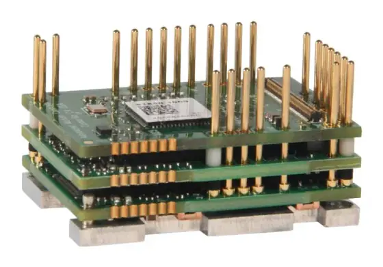
| PCB-mount / embedded drive | Low-voltage DC | OEM boards, instruments, robot joints | Solder or edge-card modules; the host board provides connectors and protection |
| Open-loop stepper drive | DC or AC input | Low-cost indexing, low speeds | No feedback; risk of lost steps under overload |
| Closed-loop stepper drive | DC or AC input | Indexing where lost steps are unacceptable | Encoder detects and corrects lost steps; lower cost than a full servo |
Representative series: AC drives such as Leadshine EL8, Kinco FD5 and Siemens SINAMICS S210; low-voltage DC drives such as Novanta Everest, Leadshine ELD3 and AMC FlexPro; multi-axis platforms such as Leadshine 4EL7-EC, Allen-Bradley Kinetix 5700 and SANMOTION R ADVANCED 400 V multi-axis; micro and PCB-mount drives such as Novanta Capitan and the IM483H/IM805H stepper modules; and stepper drives such as Leadshine CS3E (closed-loop EtherCAT) and EM3E.
If you are still deciding the motor technology, read servo vs stepper first.
How to size a servo drive: current
Drives are rated in current, not torque. The method:
- Build the motion profile: acceleration, constant speed, deceleration and dwell, with times.
- Calculate the motor torque in each segment (inertia × angular acceleration, plus friction and gravity load).
- Convert torque to current with the motor torque constant: I = T ÷ Kt.
- Calculate RMS current over the whole cycle: I_rms = √(Σ I²·t ÷ Σ t). This is the thermal load and must sit within the drive’s continuous rating. Linear Motion Tips explains why RMS, not average, is the right measure of heating.
- Take the highest instantaneous current as the peak; check it against the drive’s peak rating and the time it can be sustained.
- Add margin. ADVANCED Motion Controls recommends at least 25% more current capacity than expected draw, for both drive and power supply.
Worked example. A motor with Kt = 0.8 Nm/Arms needs 2.4 Nm RMS over the cycle and 7.2 Nm peak during acceleration. That is 3.0 Arms continuous and 9.0 Arms peak. With 25% margin, choose a drive rated at least 3.75 Arms continuous and 11.25 Arms peak.
Unit trap: some datasheets rate Kt and drive current in Arms, others in amps peak of the sine wave. They differ by √2 (about 1.41). Mixing them is one of the most common sizing errors.
Voltage: the bus voltage must exceed the motor’s back-EMF at top speed (Ke × ω) with headroom for current regulation. AMC suggests around 25% margin above back-EMF, and points out that an unregulated DC supply rises with mains voltage, which eats into the gap below the drive’s overvoltage limit.
Regeneration and braking resistors
When a motor decelerates a load, or lowers one, it acts as a generator and pushes energy back onto the drive’s DC bus. The bus capacitors absorb a little; beyond that, the voltage rises until the drive trips on overvoltage unless a braking (shunt) resistor burns the energy off, or a regenerative supply returns it to the mains.
The energy per stop is E = ½ J (ω₁² − ω₂²), plus m·g·h for vertical axes. The capacitor window is E_cap = ½ C (V_max² − V_nom²).
Worked example. A total reflected inertia of 0.01 kg·m² stopping from 3,000 rpm (314 rad/s) returns about 490 J. A 230 VAC drive has a nominal bus of about 325 V; with 1,000 µF of bus capacitance and a braking threshold of 390 V, the capacitors can absorb only about 23 J. A resistor is clearly needed. If the axis stops once every 2 seconds, average resistor power is about 245 W; if it stops in 0.2 s, peak power is about 2.5 kW.
Following Novanta’s shunt sizing method: average power = energy per stop × stops per second; peak power is the larger of energy ÷ deceleration time and V_max² ÷ R; and apply the resistor’s temperature derating. For mains drives, never go below the minimum resistance in the drive manual, or the braking transistor will be overloaded. Multi-axis drives on a shared DC bus can reduce resistor size, because one axis’s braking energy can be used by another that is accelerating at the same time.
Fieldbus: EtherCAT, CANopen and PROFINET
- EtherCAT processes frames on the fly as they pass through each node, giving cycle times of 100 µs or less and jitter under 1 µs, with free choice of line, tree or star topology (Hilscher). It is the default for multi-axis motion on CODESYS and many PC-based controllers.
- CANopen is slower but simple, low-cost and robust, which is why it is common on AGVs, mobile robots and battery-powered machines.
- PROFINET RT runs at cycle times around 1 ms; IRT, which needs Conformance Class C devices and switches throughout, goes down to 250 µs and below for closed-loop motion (PROFINET University).
- EtherNet/IP with CIP Motion is the native choice on Rockwell Logix platforms.
- Pulse/direction and analogue ±10 V remain useful for simple controllers, retrofits and PLCs with pulse outputs.
The CiA 402 drive profile defines a standard state machine and modes of operation (profile position, profile velocity, homing, and cyclic synchronous position, velocity and torque). It runs over CANopen and over EtherCAT as CoE. KEB warns that “CiA 402 compliant” can mean partial support, so confirm the specific modes and homing methods your controller uses.
STO and functional safety
Safe Torque Off is the baseline safety function in IEC 61800-5-2. Two independent channels block the power stage, so the motor cannot produce torque, and it coasts to a stop (stop category 0). Many servo drives rate their STO up to SIL 3 / PL e; check the actual rating and the wiring conditions it depends on. Points engineers often miss:
- STO does not isolate the drive. Invertek states that high voltage can still be present at the power terminals, so isolate before electrical work.
- STO does not brake. For a controlled stop use SS1 (decelerate, then STO); for vertical axes add a holding brake and Safe Brake Control so the load cannot drop.
- Higher functions such as safe limited speed or safe position need a safety-rated encoder and often a safety fieldbus such as FSoE or PROFIsafe.
The required SIL or PL comes from your machine risk assessment, not from the drive datasheet.
Common servo drive mistakes
- Sizing on motor rated current rather than the real RMS of the duty cycle.
- Mixing Arms and Apeak ratings.
- Ignoring regeneration until overvoltage trips appear in commissioning.
- Choosing a drive that does not read the motor’s encoder protocol.
- Assuming STO makes the machine safe to work on.
- Underestimating cable length effects: voltage drop, reflected-wave stress on long motor cables and encoder signal quality.
What to send us for a drive quote
- Motor make and model (or torque, speed and inertia if the motor is not chosen yet)
- Motion profile: move distances, times, dwell, duty cycle; vertical or horizontal
- Supply available: mains voltage and phases, or DC bus voltage
- Encoder type and protocol
- Controller and fieldbus; required CiA 402 modes
- Safety functions and target SIL/PL
- Number of axes and cabinet constraints; IP rating if machine-mounted
- Annual volumes
Start in the spec builder and our engineers will propose matched drive, motor and feedback combinations from our supply network.
Guides
Where servo drives are used
What we need to know to specify servo drives
These are the questions an applications engineer works through first. Approximate answers are fine: ranges narrow the options quickly, and we confirm the details with you.
- Axes: 1, 2–4, 5 or more
- Motor type: Brushless servo, Brushed DC, Stepper, Linear motor
- Network: EtherCAT, CANopen, PROFINET, Modbus, Pulse / direction
- Supply: 24–80 V DC, 230 V AC, 400 V AC
We also ask about the environment (washdown, outdoor, subsea, ATEX, vacuum, shock and EMC), annual quantities and timescale, because these decide whether a standard, modified or custom design is the best fit.
158 series compared
Series from 44 manufacturers, grouped by type. Figures are the highest published for each series. Open a series for the full specification and, for brands outside our supply network, the alternatives that meet or exceed it.
AC servo drive (55)
Multi-axis servo drive (31)
PCB-mount drive (24)
DC servo drive (15)
| Brand | Series | Continuous current | Peak current | Power |
|---|---|---|---|---|
| Leadshine | ELD2 Series Low-Voltage DC Servo Drives | 60 A | 180 A | 2,500 W |
| Leadshine | ELD3 Series Miniature DC Servo Drives | 20 A | 50 A | 750 W |
| Kinco | OD Series Mini DC Servo Drives (OD114S/124S/134S) | 20 A | — | 750 W |
| Kinco | FD1 (FDxS) Series Low-Voltage DC Servo Drives (FD114S-FD164S) | 20 A | — | 1,500 W |
| Beckhoff Automation | EL72xx / ELM72xx servo terminals | 8 A | 16 A | — |
| maxon | ESCONlegacy | 10 A | 30 A | — |
| maxon | ESCON2 | — | — | 1,800 W |
| Elmo Motion Control | Gold Solo Whistle | 20 A | — | 1,600 W |
| Elmo Motion Control | Platinum Solo Bell | 25 A | — | 2,000 W |
| Allient | Pyxmos Module servo drive | 15 A | — | 1,350 W |
| Copley Controls | Accelnet PLUS Panel (BEL/BPL/BML) | 15 A | 30 A | — |
| Synapticon | SOMANET Integro | 20 A | 40 A | 4,500 W |
| Nanotec | N5 motor controller | 18 A | 40 A | — |
| ElectroCraft | PRO Series programmable DC drives | 50 A | 90 A | — |
| ElectroCraft | CompletePower Plus Universal and EZ drives | 40 A | 100 A | — |
Fieldbus stepper drive (12)
| Brand | Series | Continuous current | Peak current | Power |
|---|---|---|---|---|
| Leadshine | Leadshine EM-CAN (EM522-CAN, EM556-CAN) | 5.6 A | — | — |
| Leadshine | Leadshine EM2RS Series | 8.2 A | — | — |
| Leadshine | Leadshine EM3E Series | 8.2 A | — | — |
| Leadshine | Leadshine 2EM3E Series | 7 A | — | — |
| Leadshine | Leadshine 2EM3EIP Series | 7 A | — | — |
| Leadshine | Leadshine 4EM3E Series | 8.2 A | — | — |
| Leadshine | Leadshine CS3E Series | 8 A | — | — |
| Leadshine | Leadshine CS2RS Series | 8 A | — | — |
| Leadshine | Leadshine 2CS3E Series | 7 A | — | — |
| Leadshine | Leadshine 2CS3EIP Series | 7 A | — | — |
| igus | dryve D1 / D2 | — | 21 A | — |
| Nanotec | C5-E motor controller | 10 A | 30 A | — |
Stepper drive (7)
| Brand | Series | Continuous current | Peak current | Power |
|---|---|---|---|---|
| Leadshine | Leadshine EM-S Series (EM415S-EM882S, EM532-MINI) | 8.2 A | — | — |
| Leadshine | Leadshine EM1 Series | 8.2 A | — | — |
| Leadshine | Leadshine DM-E / DMA / DM high-voltage Series | 8.2 A | — | — |
| Leadshine | Leadshine 3DM Series (3-phase) | 11.7 A | — | — |
| Leadshine | Leadshine DM5 Series (5-phase, pulse and EtherCAT) | 4.2 A | — | — |
| Novanta | Novanta IMS MForce (MicroDrive / PowerDrive) | 7 A | — | — |
| Trinamic (Analog Devices) | TMCM-1211 (StepRocker) | 5.7 A | — | — |
Linear motor drive (6)
| Brand | Series | Continuous current | Peak current | Power |
|---|---|---|---|---|
| Kinco | DD2S Series Linear Motor Drivers | 11 A | 27.5 A | — |
| LinMot | C1100 (C1100-GP / C1150) | — | — | — |
| LinMot | C1200 (C1250 / C1250-MI / C1251) | — | 25 A | — |
| LinMot | E1200 (E1200-GP / E12xx) | 12 A | 32 A | — |
| LinMot | E1400 (E1400-GP / E1430 / E1450) | — | — | — |
| ACS Motion Control | NPMpm NanoPWM | 13.3 A | 40 A | — |
Miniature stepper drive (4)
| Brand | Series | Continuous current | Peak current | Power |
|---|---|---|---|---|
| UIRobot | UI Robot UIM240 (Pulse/Direction) | 8 A | — | — |
| UIRobot | UI Robot UIM241 (RS232) | 8 A | — | — |
| UIRobot | UI Robot UIM242 (CANbus) | 8 A | — | — |
| UIRobot | UI Robot UIM243 (Speed Control) | 8 A | — | — |
Closed-loop stepper drive (3)
| Brand | Series | Continuous current | Peak current | Power |
|---|---|---|---|---|
| Leadshine | Leadshine CS-D Series | 8 A | — | — |
| Leadshine | Leadshine CS1 Series | 8 A | — | — |
| Trinamic (Analog Devices) | TMCM-1316 | 5.7 A | — | — |
Servo drives (1)
| Brand | Series | Continuous current | Peak current | Power |
|---|---|---|---|---|
| ADVANCED Motion Controls | AxCent Analogue Servo Drives (AB, AZ, AV, B, AVB) | 150 A | 250 A | — |
Summarised from manufacturers' published data. Always confirm against the current datasheet; an engineer will check the fit before recommending anything.
Brands
Engineer support
Talk to an engineer about servo drives
Tell us what you need, whether it is this part, an equivalent or a complete axis built around it. An engineer will review your requirements and reply, normally within one working day.
- Reviewed by an engineer, not an autoresponder
- Like-for-like and better-fit alternatives
- Standard, modified and custom options
Prefer to configure it? Use the spec builder.
From component to working requirement
Applications and engineering services
Explore selection questions, replacement routes and complete motion packages. Keep the application requirements alongside the product specifications.
Complete servo motor, drive and gearbox packages
Choose the axis from the load backwards. A matched package is a defined combination of components and interfaces, with the scope of supply agreed before purchase.
Custom and modified motion control components
A standard component with the right options may solve the problem. Establish that route before committing to a modified or fully custom design.
Motors and drives for AGV and AMR traction
A traction selection needs wheel torque and speed across the vehicle duty. Battery limits, regeneration, gearing, holding and steering arrangements also matter.
Electric actuators for presses and assembly
An electric press needs a force-versus-position and time description. Peak thrust alone does not size the actuator, motor, structure or control system.