
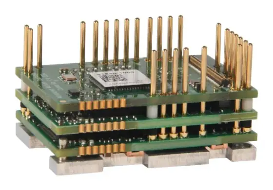
In short:Choose a multi-axis drive when several axes of similar size sit in one cabinet and move together, so they can share a rectifier, DC bus and braking resistor; then check each axis's continuous and peak current against its own channel (they are not always equal), size regeneration for the worst case where every axis stops at once, and make sure the STO arrangement matches the safety zones in your risk assessment.
What a multi-axis drive is
A multi-axis servo drive puts two, four or more inverter stages in one housing, sharing a rectifier, a DC bus, a braking (regen) resistor, logic supply and usually one fieldbus connection. The alternative is a row of single-axis drives, each with its own rectifier and resistor, or a modular system with a supply module and separate axis modules on a common bus bar.
Make the decisions in this order:
- Grouping: which axes belong on a shared drive.
- Axis count and channel ratings: match motors to channels.
- Supply and DC bus: voltage, phases, rectifier capacity.
- Regeneration: capacitor storage, resistor, sharing.
- Safety: STO and other functions, per axis or per group.
- Feedback and interface: encoders, fieldbus, I/O.
- Cabinet: width, heat, wiring.
For single-axis sizing, see how to select a servo drive.
Which axes to group
Good candidates share a cabinet, are of similar power and work together: the X, Y, Z and rotary axes of a gantry, the two motors of a gantry pair, the two wheels of a differential-drive AGV. Leadshine’s 2ELD2, for instance, adds gantry synchronisation on a two-axis DC drive, and Kinco’s FDS is a two-in-one drive aimed at AGV differential wheels.
Poor candidates are axes in different machine modules, axes in different safety zones, and a mix of one large and several very small axes where the large one would force an oversized drive.
Axis count and per-axis ratings
Check each motor against the channel it will use:
- Continuous current: motor RMS current over the cycle ≤ the channel’s rated current.
- Peak current: motor peak current demand ≤ the channel’s peak.
- Channel differences: Leadshine’s 4EL7-ECA05 has one 750 W channel (4.3 A rms, 16.6 A peak) and three 400 W channels (2.5 A rms, 9.1 A peak) (Leadshine).
- Total rectifier capacity: the sum of simultaneous demands must not exceed what the shared input can supply. Check the drive’s total input rating, not just the per-axis figures.
Leave a spare channel only if you will use it. An unused channel is cabinet space and cost; a missing one means a second drive.
Shared DC bus and regeneration sharing
When a servo decelerates, the motor acts as a generator and returns energy to the DC bus:
E = ½ × J × ω²
where J is the total inertia (motor plus reflected load, kg·m²) and ω the speed (rad/s), less friction and losses. The bus capacitors can store some of it:
E_caps = ½ × C × (V_max² − V_nom²)
where V_nom is the normal bus voltage and V_max the level at which the braking chopper switches in. Anything above E_caps goes to the braking resistor as heat.
On a shared bus, three things change (Motion Control Tips, Kollmorgen):
- The bus absorbs more. Shared capacitance stores more energy.
- Axes trade energy. If one axis regenerates while another motors, the net returned energy can approach zero. Check the timing of the cycle: whether decelerations coincide with accelerations elsewhere.
- Worst case is a full stop. In an emergency or process stop, every axis can decelerate at once. The peak requirement is then the sum of each axis’s peak regenerated power, and the resistor must keep the bus below its fault level. Do not credit capacitor storage in that case, because the bus state before a stop is not guaranteed.
Kollmorgen’s method sizes the resistor for continuous power (total energy per cycle over the cycle time, less capacitor storage) and peak power (energy per deceleration over deceleration time) separately, and notes that resistor peak ratings are often around 10 to 15 times their continuous rating.
Many multi-axis drives share one built-in resistor; the 4EL7-ECA05 uses a shared rectifier module and regenerative resistor (Leadshine). Schneider notes for its Lexium 32 that several drives can share one properly rated external resistor when buses are linked (Schneider Electric). Linking the buses of separate drives yourself is a different matter: it needs the maker’s application note for fusing, precharge and supply rules.
Vertical axes regenerate continuously while lowering. Power = m × g × v, less friction. A 10 kg load lowered at 0.5 m/s returns about 49 W for as long as it moves. That is continuous resistor duty unless another axis is using it.
Safety: STO and zoning
STO (safe torque off) removes torque-producing power from the motor and corresponds to stop category 0 of EN/IEC 60204-1; SS1 (stop then STO) corresponds to stop category 1. Both are defined in IEC 61800-5-2 (Pilz).
On a multi-axis drive, the question is scope:
- STO common to all axes: the 4EL7-EC has two STO circuits common to all four axes. An STO demand stops every axis on that drive.
- STO per axis or per pair: allows one axis to be safely stopped while others run.
- Optional STO: some multi-axis stepper and servo drives offer STO only as an option (Leadshine’s 2EM3E and 2CS3E, for example).
Map the drive’s STO scope to the safety zones in your risk assessment. A loading station where an operator reaches in while the rest of the cell keeps running needs that axis on its own STO channel. Confirm the certified performance level or SIL in the manual; Leadshine lists SIL3 STO on the 2ELD2.
Vertical axes need a holding brake and, usually, a safe brake control strategy: STO removes torque, and the load falls if the brake does not hold.
Feedback, interface and I/O
- Encoders: one input per axis; check the type. The 4EL7-EC takes 23-bit serial absolute encoders; the 2ELD2 accepts incremental, 17-bit absolute magnetic, BiSS-C and Tamagawa absolute and Hall UVW.
- Fieldbus: EtherCAT is common on multi-axis drives because one node carries several axes with distributed-clock synchronisation well under 1 µs (ETG). Check that the controller supports multi-axis nodes (several CiA 402 axes in one device).
- I/O: shared I/O is limited (the 4EL7-ECA05 has 4 inputs and 2 outputs for all four axes). Limit and home switches for four axes may need remote I/O.
- Brake outputs: count them. The 4EL7-EC provides direct brake terminals.
Cabinet space and heat
A multi-axis drive saves width, terminals and duct, and simplifies power wiring. Leadshine says the 2ELD2 saves around 30% of installed volume compared with two single drives. Heat is not saved: the inverter losses of every axis are still in the cabinet, and a shared resistor concentrates braking heat. Size cabinet cooling on total losses plus resistor dissipation, and mount external resistors outside the cabinet where possible.
Plan for service. A fault on one channel may require replacing the whole unit and re-commissioning every axis on it. Keep parameter backups for all axes together.
Worked example: four-axis gantry on 230 VAC
Requirement. Pick-and-place gantry: X (long axis), Y, Z (vertical, 10 kg moving) and a rotary R. All axes in one cabinet, EtherCAT to a motion controller, single-phase 230 VAC. Operators load trays outside a light curtain; the whole gantry stops if the curtain is broken. Motor sizing (done earlier) gives X at 750 W and Y, Z, R at 400 W each.
Channel match. A four-axis drive with one 750 W channel and three 400 W channels fits exactly; the 4EL7-ECA05 has that split. Check each motor’s RMS and peak current against 4.3 A / 16.6 A (X) and 2.5 A / 9.1 A (Y, Z, R).
Regeneration (illustrative values; use your motor and drive data).
- X: total inertia 12 kg·cm² (0.0012 kg·m²) at 3,000 rpm (314 rad/s): E = ½ × 0.0012 × 314² ≈ 59 J per stop.
- Y: 6 kg·cm² at 3,000 rpm: ≈ 30 J.
- Bus storage: assume 1,000 µF, a nominal bus of 325 V (230 V × √2) and a chopper threshold of 380 V: E_caps = ½ × 0.001 × (380² − 325²) ≈ 19 J.
On separate drives, the X drive would send about 40 J per stop to its resistor even if Y were accelerating at that instant. On the shared bus, the X deceleration can feed Y’s or Z’s acceleration if the cycle overlaps them.
Worst case. An E-stop with all axes at speed: about 59 + 30 + Z + R, with no capacitor credit. If X and Y decelerate in 0.1 s, peak regenerated power is about (59 + 30) / 0.1 ≈ 890 W plus Z and R. Check this against the built-in resistor’s peak rating; add an external resistor if needed.
Z lowering. 10 kg at 0.5 m/s returns about 49 W continuously while lowering. In this cycle Z lowers while X and Y move, so most of it is shared.
Safety. One zone for the whole gantry, so STO common to all four axes suits the risk assessment. Z needs a holding brake and a brake test routine.
I/O. Four home switches and four pairs of limit switches exceed the drive’s 4 inputs; use EtherCAT remote I/O near the gantry.
Result. One four-axis EtherCAT drive in place of four single drives, with the regen case checked for an all-axis stop, a Z-axis brake, and remote I/O for the switches.
Products in our range to consider
- Leadshine 4EL7-EC: four-axis EtherCAT AC servo drive, 400–1,500 W per axis on 220 or 400 VAC, two STO circuits common to all axes.
- Leadshine 2EL6-EC: two-axis EtherCAT AC servo drive, 400–1,500 W per axis, two encoder inputs.
- Leadshine 2ELD2: two-axis DC servo drive for 24–70 VDC, 20 or 30 A rms per axis, gantry synchronisation, SIL3 STO.
- Kinco FDS: two-in-one low-voltage DC servo drive for AGV differential wheels, CANopen or pulse, brake output.
- Leadshine 2CS3E: dual-axis EtherCAT closed-loop stepper drive with optional STO, for lower-cost auxiliary axes.
- Leadshine 4EM3E: four-axis open-loop EtherCAT stepper drive, up to 8.2 A per axis.
- Leadshine EL8: single-axis AC servo drives, EtherCAT or RS, for axes that do not suit a shared drive.
- Kinco AK: CODESYS EtherCAT motion controller for up to 32 synchronised axes on a 1 ms cycle.
- Leadshine MC500: CODESYS EtherCAT motion controller for 8, 16 or 32 axes plus local pulse axes.
What else the build needs
- Servo motors with matching encoders and brakes: see servo and stepper motors and how to select a servo motor.
- Motion controller supporting multi-axis EtherCAT nodes: see motion controllers and how to select a motion controller or PLC.
- Braking resistor sized for the all-axis stop, mounted for cooling.
- Mains protection: fuses or breakers to the drive maker’s rating, mains filter, and contactor if required.
- Safety relay or controller wired to STO.
- Remote I/O for limit and home switches: see how to select an HMI and remote I/O.
- Motor and feedback cables, shielded and of the specified length.
Things that catch engineers out
- Assuming all channels are equal. Check each axis’s current against its own channel.
- Sizing regen for the normal cycle only. An E-stop puts every axis into regeneration at once.
- Crediting capacitor storage in the stop case. The bus may already be high.
- STO scope that does not match safety zones. Common STO stops everything on the drive.
- Running out of I/O. Shared drives have few inputs for many axes.
- Concentrating heat. Fewer boxes, same losses, plus a shared resistor.
- Linking DC buses of separate drives without the application note. Fusing and precharge rules matter.
- Service impact. One failed unit takes several axes down; keep parameter backups.
Checklist
Send these to our engineers, or enter them in the spec builder:
- Number of axes and which ones share a cabinet and a safety zone
- For each axis: motor model, RMS and peak current, encoder type, brake
- Supply: voltage, phases, available current
- Move cycle for each axis, showing when axes accelerate and decelerate together
- Load inertia and top speed of each axis, and any vertical axes with their mass and lowering speed
- Emergency and process stop behaviour required
- Safety functions (STO, SS1) per axis or per group, and target PL or SIL
- Fieldbus and controller model
- I/O per axis: home, limits, probes
- Cabinet space and cooling limits
- Ambient temperature
For the wider family, see our servo drives overview.
Frequently asked questions
What is the advantage of a multi-axis servo drive?
Fewer boxes and shared power stages. Two or four axes share one rectifier, DC bus, braking resistor, supply wiring and network connection. That saves cabinet width, wiring and cost per axis, and lets energy from a decelerating axis feed one that is accelerating. Leadshine says its two-axis 2ELD2 saves around 30% of installed volume compared with two single drives.
How does a shared DC bus save energy?
A decelerating servo returns kinetic energy to the DC bus. On a separate drive, anything the bus capacitors cannot store is burnt in a braking resistor. On a shared bus, another axis that is accelerating at the same moment uses it instead. Kollmorgen's guidance notes that the net returned energy can approach zero when axes are phased that way, but that in a full machine stop all axes decelerate together.
Do all axes on a multi-axis drive have the same rating?
Not always. Leadshine's 4EL7-ECA05 four-axis EtherCAT drive, for example, has one 750 W channel at 4.3 A rms and three 400 W channels at 2.5 A rms. Check each axis's motor against its own channel's continuous and peak current, and plan which motor goes on which output before ordering.
Can I stop one axis safely on a multi-axis drive while the others run?
Only if the drive has STO per axis or per group that matches your zones. The 4EL7-EC has two STO circuits common to all four axes, so an STO demand stops every axis on that drive. If a risk assessment needs one axis safely stopped while others keep moving, choose drives with independent STO channels or split those axes onto separate drives.
When should I use separate single-axis drives instead?
When axes are very different in power, are spread across separate machine modules or cabinets, need independent safety zones, or must be serviced and replaced independently without stopping the rest. A fault on a multi-axis drive can take all its axes down, and replacing it disturbs every axis. Separate drives also make spares simpler when axes are of mixed sizes.
Sources
- Motion Control Tips (Hurley Gill, Kollmorgen): Selecting regenerative resistors to harvest servomotor energy
- Leadshine: 4EL7-ECA05 four-axis EtherCAT AC servo drive
- Schneider Electric: Common DC bus (Lexium 32 help)
- Pilz: International standard EN / IEC 61800-5-2 (safety functions and stop categories)
- EtherCAT Technology Group: EtherCAT technology overview
Figures are summarised from the sources above and from manufacturers' published data on the date shown. Always confirm against the current datasheet for your exact part.