
In short:Start from the motor, not the drive: match the drive's supply and bus voltage to the motor winding, its continuous current to the motor's rated current and its peak current to the torque peaks in your move. Then confirm it reads your encoder, speaks your fieldbus, has the safety functions your risk assessment needs and can absorb the energy the axis returns when it brakes.
A servo drive turns a command from your controller into precisely regulated current in the motor winding, closing current, velocity and often position loops on the motor’s feedback. Picking one is mostly a matching exercise. Get the motor right first (see servo vs stepper if that decision is still open), then work through the steps below in order.
Step 1: Confirm the motor type and feedback
The drive has to commutate and control the motor you have chosen. Check:
- Motor type. Three-phase brushless (AC servo or low-voltage BLDC/PMSM) is the default. Some drives also run brushed DC, voice-coil, slotless or linear motors; others are locked to the maker’s own motor range. Linear motors and direct-drive torque motors often need a drive with specific commutation-finding routines and a second encoder input.
- Feedback protocol. Incremental TTL with Halls, sin/cos 1 Vpp, resolver, and serial absolute protocols such as BiSS-C, EnDat 2.2, Hiperface, SSI, Tamagawa and Nikon A-format are all common. A drive that does not read your encoder’s protocol will not work, whatever its power rating. If you need multi-turn absolute position without homing, confirm the drive supports the multi-turn data and, where relevant, any backup battery.
- Dual-loop (full closed-loop) control. If you want the position loop closed on a linear scale or load-side encoder to remove screw or belt error, the drive needs a second encoder input. See absolute vs incremental encoders.
Kollmorgen’s advice is to buy the drive and motor as a matched system where you can, because the ratings and motor parameters are designed to work together (Kollmorgen).
Step 2: Match supply and DC bus voltage
The supply sets the DC bus voltage the drive can apply to the winding, and therefore the speed the motor can reach before back-EMF uses up the available voltage.
| Supply | Approximate DC bus | Typical use |
|---|---|---|
| 24–48 V DC (some to 60–90 V) | Equal to supply | AGVs, cobots, battery machines, embedded axes |
| 1-phase 230 V AC | about 325 V DC (230 × √2) | Machine axes up to roughly 2 kW |
| 3-phase 400 V AC | about 565 V DC (400 × √2) | Larger axes, multi-kW machines |
The motor winding must be specified for that bus. A motor wound for a 565 V bus on a 325 V bus will run out of speed early; a low-voltage winding on a high-voltage drive risks insulation and over-current faults. For DC drives, check the drive’s maximum input voltage against the supply’s worst case, including regenerated voltage, not just its nominal value.
Step 3: Size continuous and peak current
From your sizing calculation you have an RMS torque (for the thermal, continuous rating) and a peak torque. Convert both to current with the motor’s torque constant, Kt (Nm/A rms):
- I_cont = T_rms ÷ Kt
- I_peak = T_peak ÷ Kt
Then apply Kollmorgen’s matching rules (Kollmorgen):
- The drive’s continuous current should meet or exceed the motor’s continuous (rated) current, so you can use the motor’s full thermal capacity.
- The drive’s peak current must cover the current at your peak torque. Most drives give two to three times their continuous rating as peak, for a few seconds or less, so check that the peak lasts as long as your acceleration.
- Many motors have a peak-to-continuous ratio of up to about 4:1. A drive with a 2:1 peak ratio may not let you use all of it.
- If the drive is larger than the motor, set its current limits to the motor’s ratings and use motor temperature monitoring.
Watch the units: drives quote current in A rms or A peak (sine amplitude), and motors may use either. A 10 A rms rating is about 14 A peak.
Step 4: Plan for regeneration and braking resistors
When the motor decelerates a load, or lowers one, it works as a generator and pushes energy back onto the DC bus. If nothing absorbs it, the bus voltage rises until the drive trips on overvoltage (Kollmorgen).
Work out the energy per event:
- Kinetic: E_k = ½ × J_total × ω² (J in kg·m², ω in rad/s)
- Potential, for a vertical axis: E_p = m × g × h
- Energy the bus capacitors can store before tripping: E_cap = ½ × C × (V_trip² − V_nom²)
If the returned energy (less mechanical and electrical losses) exceeds E_cap, you need a braking (shunt, regen) resistor, a shared DC bus with other axes that are motoring at the same time, or a regenerative supply. Novanta’s method sizes the resistor from the drive’s shunt current, R ≈ 1.1 × V_max ÷ i_shunt, then checks average power (energy per stop × stops per second) and peak power, with derating for temperature (Novanta). For mains drives, follow the minimum resistance and fusing in the drive’s installation manual. Check whether the drive has an internal resistor and what continuous power it is rated for before relying on it.
On battery-powered DC systems, regenerated energy can push the bus above the battery or power supply’s limit. Many bench supplies cannot sink current at all, so specify a shunt regulator or confirm the battery management system accepts charge.
Step 5: Choose the command interface and fieldbus
Use what your motion controller or PLC already masters:
- EtherCAT with the CiA 402 drive profile (CoE) is the common choice for multi-axis machines. The EtherCAT Technology Group designs for cycle times of 100 µs or less and distributed-clock jitter well under 1 µs (EtherCAT Technology Group).
- CANopen (CiA 402) is simple and robust for smaller low-voltage machines, AGVs and embedded systems, with lower bandwidth.
- PROFINET (with the PROFIdrive profile) and EtherNet/IP (CIP Motion) suit plants standardised on Siemens or Rockwell controllers.
- Modbus RTU or RS485 position tables suit simple indexing axes.
- Pulse and direction or ±10 V analogue still work for retrofits and simple controllers, but you lose drive diagnostics and parameter access.
If you plan to cascade safety over the network, check for FSoE (Safety over EtherCAT) or PROFIsafe support, not just the base fieldbus.
Step 6: Specify STO and other safety functions
Safe Torque Off is defined in IEC 61800-5-2. It removes the drive’s ability to produce torque in hardware, using two independent channels, and corresponds to a stop category 0, uncontrolled coast (Synapticon). Many drives offer STO rated SIL 3 / PL e, which lets you remove motor contactors from the safety circuit.
STO is not a brake. Your risk assessment sets the safety functions and levels you need:
- SS1 (Safe Stop 1): controlled deceleration, then STO.
- SBC (Safe Brake Control): closes the holding brake before torque is removed. Essential on vertical or gravity-loaded axes.
- SLS, SOS, SS2: limited speed and safe operating stop, typically needing safe feedback and a drive with an extended safety module.
State the required SIL or PL and category to the supplier, and confirm whether the function is built in, needs an option card or relies on an external safety relay.
Step 7: Form factor, environment and tuning
- Panel drives are finished, approved units for a cabinet, with connectors and heatsinks. Fastest to design in.
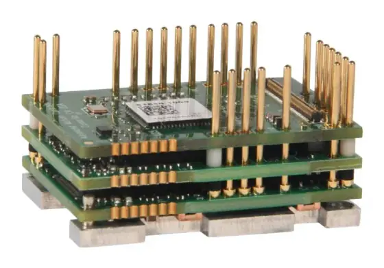
- PCB-mount and embedded drives plug or solder onto your own board. They save space and cost at volume in robot joints, AGVs, gimbals and medical devices, but you own the connector design, thermal path and EMC.
- Multi-axis drives (two or four axes in one housing) save panel width and wiring on gantries and multi-axis machines.
- Environment: check ambient temperature and derating, IP rating (panel drives are commonly IP20 and need a cabinet), altitude, vibration and conformal coating needs.
- Tuning: look for auto-tuning, notch filters, vibration suppression and a free set-up tool with a scope function. On belt axes and high inertia ratios these features save days of commissioning. Ask for current-loop and velocity-loop bandwidth if the axis is highly dynamic.
Worked example: a vertical ball-screw axis on 230 V
Axis: vertical Z axis, moving mass 25 kg, ball screw with 10 mm lead, screw efficiency taken as 0.9. Peak speed 0.5 m/s (3,000 rpm), accelerating in 0.1 s. Stroke 0.3 m, one down stroke every 5 s. Supply 1-phase 230 V AC.
Torques at the motor (T = F × lead ÷ (2π × η)):
- Holding against gravity: F = 25 × 9.81 = 245 N, so T = 245 × 0.01 ÷ (2π × 0.9) ≈ 0.43 Nm
- Accelerating upwards at 5 m/s²: F = 25 × (9.81 + 5) = 370 N, so T ≈ 0.65 Nm
- Motor rotor plus screw inertia, assumed 0.5 × 10⁻⁴ kg·m², at α = 5 × 2π ÷ 0.01 ≈ 3,140 rad/s² adds about 0.16 Nm
- Peak ≈ 0.81 Nm, and the axis needs about 0.43 Nm continuously whenever it holds position
Motor and drive. Assume a typical 400 W, 60 mm AC servo motor with 1.27 Nm rated torque, about 3.8 Nm peak and 2.8 A rms rated current (Kt ≈ 0.45 Nm/A). Peak current needed is 0.81 ÷ 0.45 ≈ 1.8 A, holding current about 1.0 A. A 400 W class 230 V drive matched to that motor covers it comfortably. Specify the motor with a holding brake, because the load must not fall on STO or power loss.
Regeneration. Each down stroke returns potential energy: 25 × 9.81 × 0.3 ≈ 74 J. Allowing for screw and motor losses, call it about 60 J back on the bus. The bus sits at about 325 V; assume a 680 µF bus capacitance and an overvoltage threshold of 390 V (read the real figures from the drive manual). E_cap = ½ × 680 × 10⁻⁶ × (390² − 325²) ≈ 16 J. That is well short of 60 J, so the axis needs a braking resistor.
- Average power: 60 J every 5 s ≈ 12 W. Allow derating.
- Power while lowering at speed: roughly m × g × v × losses ≈ 25 × 9.81 × 0.5 × 0.8 ≈ 100 W for most of the stroke, plus a short peak when stopping.
A small external resistor of around 50–100 W rating, at no less than the drive’s stated minimum resistance, is a sensible starting point; confirm against the drive’s own sizing procedure.
Safety. The risk assessment for a vertical axis typically asks for SS1 plus safe brake control, not STO alone. That steers you to a drive with STO and a brake output at minimum, or a drive with SBC.
Candidates: a Leadshine EL8 with an ELM brake motor on EtherCAT, or a Kinco JD2 with an SMK motor.
Products in our range to consider
- Leadshine EL8 AC servo drives: 220 V AC drives from 400 W to 2 kW with 3.5 kHz bandwidth, STO SIL 3 and a second encoder input, in EtherCAT or Modbus/pulse versions.
- Leadshine EL7S / EL7 AC servo drives: 220 V and 400 V platform from 400 W up to 22 kW, all with STO, in EtherCAT, Modbus/pulse or PROFINET variants.
- Kinco JD2 AC servo drives: 50 W to 7.5 kW, up to 26 A continuous and 65 A peak, reads BiSS, EnDat, Nikon A and optional resolver feedback, with STO SIL 3 / PL e on every model.
- Kinco FD5P PRO AC servo drives: 220 or 380 V drives to 7.5 kW with 17/23-bit absolute feedback in RS485, EtherCAT or PROFINET versions; mid and high power models have a built-in brake resistor.
- Leadshine ELD3 miniature DC servo drives: 76 × 50 × 33.5 mm, 24–70 V DC, 50–750 W, with STO and support for brushed, slotless, voice-coil and linear motors.
- Kinco FD1 low-voltage DC servo drives: 24–60 V DC, 50 W to 1.5 kW, in pulse, CANopen and EtherCAT versions.
- ADVANCED Motion Controls FlexPro: 10–90 V DC drives up to 100 A continuous and 200 A peak in PCB, embedded and panel formats, STO standard.
- ADVANCED Motion Controls DigiFlex Performance: 10–747 V DC and 120–480 V AC drives up to 150 A continuous and 250 A peak, including PCB and vehicle-mount versions.
- Novanta Everest: 8–72 V DC, 45 A continuous, 60 A peak, up to 5 kW, as a core module, PCB-mount board or connectorised unit.
- Novanta Capitan: an 18 g micro servo drive for 8–60 V DC at 10 A continuous and 20 A peak, with BiSS-C feedback and STO SIL 3.
What else the build needs
- Motor: matched winding and connector set. See servo and stepper motors.
- Feedback: the motor encoder, plus a load-side scale for dual-loop control. See encoders.
- Brake: a spring-applied holding brake for vertical axes, with a drive brake output or SBC.
- Gearing: a planetary or strain-wave gearbox to match load inertia and torque. See gearboxes and harmonic vs planetary vs cycloidal.
- Braking resistor or shared DC bus for regenerative loads.
- Cabling: shielded motor and feedback cables of the right length and flex rating; drag-chain rated if the axis moves.
- Slip ring for continuously rotating axes carrying power, feedback or EtherCAT. See Ethernet through slip rings.
- Controller and safety relay or safety PLC. See motion controllers.
- Power supply: mains filter and fusing, or a DC supply able to handle regenerated energy.
Things that catch engineers out
- Mixing rms and peak current. A drive rated 10 A peak is not equivalent to a motor rated 10 A rms.
- Assuming STO holds the load. It does not. Vertical axes need a brake and correct sequencing.
- Ignoring regen until commissioning, then finding the drive trips on overvoltage on the first fast stop or lowering move.
- Choosing a fieldbus the controller does not master, or a drive that supports EtherCAT but not the operating modes (CSP, CSV, CST) your controller uses.
- Feedback protocol mismatch, especially with third-party motors or replacement encoders.
- Temperature derating. A drive rated at 40 °C ambient may lose a large share of its continuous current in a hot, sealed cabinet.
- Battery systems that cannot accept regenerated current, or a DC supply that latches off when the bus rises.
Checklist
Send these to our engineers, or enter them in the spec builder:
- Motor make, model and winding, or the torque and speed it must deliver
- Feedback type and protocol, and whether you need a second encoder input
- Supply: DC voltage range (with battery limits) or AC phases and voltage
- RMS and peak torque or current, and how long each peak lasts
- Load inertia, any vertical or gravity load, stops per minute
- Fieldbus or command interface, and the controller brand
- Safety functions and the SIL or PL level from your risk assessment
- Form factor: panel, PCB-mount or embedded; number of axes per unit
- Ambient temperature, IP rating, vibration and approvals needed
- Annual volume and cost target per axis
Frequently asked questions
How do I size a servo drive for a servo motor?
Use the motor datasheet. The drive's supply voltage must suit the motor winding, its continuous current should meet or exceed the motor's rated current, and its peak current must cover the current your peak torque needs for as long as that peak lasts. Kollmorgen notes most drives give two to three times continuous current as peak for a few seconds. Then check feedback and fieldbus compatibility.
Can I use a bigger servo drive than the motor needs?
Yes, but limit the current in the drive's motor parameters so it cannot push more than the motor's peak rating into the winding, and use motor temperature monitoring. Kollmorgen recommends that protection when the drive's continuous rating exceeds the motor's. An oversized drive also costs more, takes more panel space and may have coarser current resolution at low torque.
When does a servo drive need a braking resistor?
When the energy the axis returns during deceleration or lowering exceeds what the drive's DC bus capacitors can absorb before the overvoltage trip. Vertical axes, high-inertia rotary tables and fast reversing cycles usually need one. Work out kinetic and potential energy per stop, compare it with the capacitor energy between nominal and trip voltage, then size resistance and power from the drive manual.
Does Safe Torque Off hold a vertical load?
No. STO removes the drive's ability to produce torque, so the motor coasts and a gravity-loaded axis will fall. A vertical axis needs a holding brake on the motor or the mechanics, controlled so it closes before torque is removed. Safe Brake Control does this sequencing; SS1 brings the axis to a controlled stop first and then applies STO.
Which fieldbus should a servo drive use?
Use the one your controller already masters. EtherCAT with the CiA 402 drive profile is common for multi-axis motion because of its short cycle times and distributed clocks. CANopen suits smaller low-voltage machines. PROFINET and EtherNet/IP fit plants built on Siemens or Rockwell controllers. Pulse and direction remains useful for simple axes or legacy controllers.
What is the difference between a PCB-mount and a panel servo drive?
A PCB-mount drive is a module that solders or plugs onto your own carrier board, so you design the connectors, power routing, cooling and EMC yourself. It saves space and cost at volume and suits robot joints, AGVs and embedded products. A panel drive is a finished, connectorised and approved unit for a cabinet, which shortens development and simplifies service.
Sources
- Kollmorgen: How to select a servo drive
- Novanta (Ingenia): Sizing a shunt resistor for regenerative braking
- Kollmorgen: Bus overvoltage faults and how to resist them
- Synapticon Motion Control Academy: Safe Torque Off (STO) and Safe Brake Control (SBC)
- EtherCAT Technology Group: EtherCAT technology overview
Figures are summarised from the sources above and from manufacturers' published data on the date shown. Always confirm against the current datasheet for your exact part.