
In short:Size a frameless joint motor from the joint's torque budget (gravity, acceleration and friction) divided by the gear ratio and efficiency, then check RMS torque against the continuous rating derated for your actual housing, using copper loss P = (T/Km)². The gear ratio, hollow bore, encoders and brake are chosen together, because each one changes the motor's heat and space budget.
Why robot joints use frameless motors
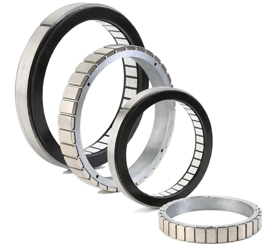
A frameless torque motor is just a stator and a rotor. You supply the housing, shaft, bearings, feedback and brake. In a robot joint that is an advantage: the stator sits in the joint casting, the rotor sits on the gearbox input, and the gear’s own output bearing carries the arm. Allient describes a conventional housed motor and coupling arrangement as more than twice as long as an integrated frameless joint for the same performance (Allient).
The cost is that you take responsibility for things a housed servo motor solves for you: air gap and concentricity, heat removal, sensor alignment and cable management. Sizing therefore has to look at the whole joint, not just the motor table.
Step 1: build the joint torque budget
Work at the joint output first. For a rotating arm joint the torque has four parts:
- Gravity: T_g = g × Σ(mᵢ × rᵢ) × cos(θ), where mᵢ is each mass beyond the joint (links, wrist, tool, payload) and rᵢ the horizontal distance from the joint axis to its centre of mass. The worst case is the arm horizontal at full reach with full payload.
- Acceleration: T_a = J × α, where J is the inertia of everything beyond the joint about the joint axis (point masses contribute m × r²) and α the angular acceleration in rad/s².
- Friction: seals, the output bearing and cable drag. The gearbox’s own losses are handled through its efficiency in Step 3.
- External loads: process forces, contact forces and, for a cobot, the collision limit you will let the joint reach before it stops.
The motor-side torque also includes accelerating the rotor and the gear’s input inertia: T = (J_rotor + J_gear_in) × α × i, where i is the ratio. At ratio 100 this is often small but not negligible.
Step 2: RMS torque, copper loss and thermal limits
A joint motor is almost always thermally limited, so size it on RMS torque over a realistic cycle:
T_rms = √( Σ Tᵢ² × tᵢ / Σ tᵢ )
Include dwell time and the torque needed during it. That is the trap in robot joints: an arm holding a payload out horizontally needs full gravity torque while standing still.
Copper loss then follows from the motor constant Km (Nm/√W), which is the torque constant divided by the square root of winding resistance (Humanoid Guide, Allient):
P_cu = (T / Km)²
Check your units: Km values on datasheets can be quoted per phase or line-to-line, and hot or cold. Kollmorgen, for example, lists Km separately at 25°C and at operating temperature (Kollmorgen). Copper resistance rises by about 0.4% per °C, so a winding at 125°C has around 40% more resistance than at 25°C and roughly 15% lower Km.
Then compare against the continuous rating, but treat it with care. Kollmorgen rates its TBM motors mounted to a defined aluminium heat sink at 25°C ambient. Allient’s advice is that supplier continuous ratings are a reference only, because the thermal resistance inside a real joint is unknown until it is modelled or measured, and motors often need derating (Allient). A sensible rule of thumb before thermal testing is to keep T_rms at or below about 70% of the published continuous torque.
Two extra heat sources are easy to miss: the brake coil while the joint is moving (the brake is energised to release it), and the gearbox losses, which also end up in the same casting.
Step 3: the gear ratio trade-off
The motor sees the output torque divided by the ratio and the gear efficiency:
T_motor = T_out / (i × η) when the motor drives the load, and roughly T_out × η / i when the load back-drives the motor (lowering a payload).
Raising the ratio:
- Cuts motor torque and heat in proportion to 1/i, so copper loss falls with 1/i².
- Raises motor speed in proportion to i, which pushes against back-EMF on a 48 V bus.
- Raises the reflected rotor inertia by i². The robot then feels heavier to push in hand-guiding and harder to stop in a collision.
- Usually lowers efficiency and back-drivability. Strain-wave efficiency also falls at low load and low temperature (Harmonic Drive).
Allient’s recommended architecture is a frameless motor with a high-ratio, zero-backlash gear, and Kollmorgen’s TBM2G range is designed to pair with standard strain-wave sets (Kollmorgen). For the gearbox choice itself, see strain-wave vs planetary vs cycloidal.
Geometry matters too: Km grows much faster with diameter than with stack length. In Kollmorgen’s TBM2G data at a 26.3 mm stack, Km goes from 0.128 Nm/√W at 50 mm diameter to 0.802 Nm/√W at 115 mm. Allient’s guidance follows: use the largest diameter and shortest length that meet the Km target.
Step 4: hollow shaft and cable routing
Cables, air lines and sometimes Ethernet run through the joint centre, so fix the bore early:
- The smallest bore in the stack sets the limit: motor rotor, gearbox, encoder and brake all have to clear it. Cup-type strain-wave sets have no central hole; you need a hollow-shaft (silk-hat or flat) set.
- Allow for cable twist. A joint rotating ±180° or more twists the loom through the bore. Use torsion-rated cable, a clamp at each end and enough free length between them. For continuous rotation, a slip ring for robotics replaces the twisting loom.
- Bore diameter competes with Km. A larger bore means less magnetic material for the same outer diameter. Kollmorgen TBM2G inner diameters run at about half the outer diameter, for example 47 mm in the 94 mm frame.
Step 5: dual encoders
Most modern joints carry two encoders (Allient):
- Motor side: high resolution, medium accuracy. It commutates the motor and closes the current and velocity loops. Hall sensors can also be used for commutation at start-up; TBM2G offers optional Hall sensors that do not add length.
- Output side: a high-accuracy absolute encoder after the gearbox. It measures the real joint angle including lost motion and wind-up, and because the joint turns less than one revolution, it gives absolute position at power-up with no battery and no homing.
The difference between the two readings, divided by the gear ratio and multiplied by gear stiffness, gives a rough joint torque estimate. Dual-track and dual-concentric off-axis encoders now combine both in one through-bore package; RLS’s AksIM-4 Dual Concentric is one example (Electronics World). See also our guide to absolute vs incremental encoders.
Step 6: brakes
A robot arm must hold its pose when power is removed. The usual answer is a spring-applied (power-off) brake on the motor side:
- Holding torque: at least the worst-case gravity torque reflected to the motor, T_g / i, with 1.5 to 2 times margin as common practice.
- Stopping: check the brake can stop the joint from full speed if your stop category relies on it, and allow for its engagement time.
- Heat and power: a released brake draws coil power continuously while the joint moves. Allient flags brake heat as part of each joint’s thermal budget.
- Packaging: a large-bore motor can house a coaxial brake inside the rotor’s envelope, shortening the joint.
Worked example: a cobot shoulder joint
Arm: 10 kg payload at 1.0 m reach. Arm links beyond the shoulder lumped as 12 kg with centre of mass at 0.45 m.
Motion: maximum joint speed 120°/s (2.09 rad/s, 20 rpm), reached in 0.4 s, so α = 5.2 rad/s². Cycle: 0.4 s accelerate, 0.8 s constant speed, 0.4 s decelerate, 2.4 s holding, all with the arm horizontal as the worst case. Total 4.0 s.
Output torque budget:
- Gravity: 9.81 × (10 × 1.0 + 12 × 0.45) = 9.81 × 15.4 = 151 Nm
- Inertia: 10 × 1.0² + 12 × 0.45² + an allowance of 1.0 for link length ≈ 13.4 kg·m²
- Acceleration torque: 13.4 × 5.2 = 70 Nm
- Peak (lifting while accelerating): 151 + 70 = 221 Nm; during deceleration 151 − 70 = 81 Nm
Gear: ratio 100 puts the motor at 2,000 rpm at full joint speed. A size 32 strain-wave set at ratio 100, such as Harmonic Drive CSG-32 (TN 178 Nm, TR 433 Nm, TA 281 Nm, TM 841 Nm) (Harmonic Drive). Peak 221 Nm is well under TR. For a hollow joint you would use the equivalent hollow-shaft set, such as SHG.
Gear life: Harmonic Drive’s average torque weights each moving segment by input speed and time. Accelerating (221 Nm, mean 1,000 rpm, 0.4 s), constant (151 Nm, 2,000 rpm, 0.8 s), decelerating (81 Nm, mean 1,000 rpm, 0.4 s):
- T_av = ((1,000 × 0.4 × 221³ + 2,000 × 0.8 × 151³ + 1,000 × 0.4 × 81³) / 2,400)^(1/3) ≈ 161 Nm, under TA 281 Nm
- Average input speed over the whole 4 s cycle = 2,400 / 4 = 600 rpm
- L10 = 10,000 h × (2,000 / 600) × (178 / 161)³ ≈ 45,000 h (Harmonic Drive LLC)
Motor torque (assuming η = 0.75; read the real value from the gear’s efficiency curve at your speed and temperature):
- Accelerating: 221 / (100 × 0.75) = 2.95 Nm, plus rotor and gear input inertia. Using CSG-32 input inertia 1.96 × 10⁻⁴ kg·m² and an assumed rotor inertia of 1.5 × 10⁻⁴ kg·m², at 520 rad/s² that adds 0.18 Nm. Peak ≈ 3.13 Nm
- Constant speed: 151 / 75 = 2.01 Nm
- Decelerating: 81 / 75 ≈ 1.08 Nm
- Holding under servo control: conservatively 2.01 Nm (static friction helps in reality)
RMS torque:
- Holding on the motor: √((3.13² × 0.4 + 2.01² × 0.8 + 1.08² × 0.4 + 2.01² × 2.4) / 4.0) = 2.08 Nm
- Holding on the brake (motor torque zero during dwell): √((3.13² × 0.4 + 2.01² × 0.8 + 1.08² × 0.4) / 4.0) = 1.38 Nm
Motor candidates (Kollmorgen TBM2G 26.3 mm stack data, Kollmorgen):
| Frame | Continuous stall torque | Km (cold) | Copper loss at 2.08 Nm RMS (Km −15% hot) | RMS / continuous |
|---|---|---|---|---|
| 094 (94 mm OD, 47 mm ID) | 3.67 Nm | 0.528 Nm/√W | (2.08 / 0.449)² ≈ 21 W | 57% |
| 115 (115 mm OD, 57.5 mm ID) | 6.03 Nm | 0.802 Nm/√W | (2.08 / 0.682)² ≈ 9 W | 34% |
The 94 mm frame meets the 70% rule of thumb while holding on the motor, and drops to 38% if the brake carries the dwell. The 115 mm frame runs much cooler and leaves headroom for a warmer enclosure or a heavier payload, at the cost of diameter and mass. Confirm the peak torque and peak current at 2,000 rpm against the motor’s torque-speed curve on your bus voltage, since the brochure does not list peaks.
Brake: gravity torque at the motor is 151 / 100 = 1.51 Nm. With 2 times margin, specify a power-off brake of at least 3 Nm holding torque that fits inside the joint bore.
Encoders: a high-resolution motor-side absolute or incremental ring encoder for commutation, and an absolute ring on the output for joint position, or a combined dual-track unit.
Comparable frameless kits in our catalogue include Akribis ADR-F for 48 V joints up to 90 mm diameter, and Akribis ADR-P for larger, high-voltage axes. Output-side ring encoders include the Renishaw RLS AksIM-4.
Common mistakes
- Leaving out the holding torque in the RMS cycle. A horizontal arm is a full-time load.
- Trusting the continuous rating as installed. Derate until the joint is thermally tested.
- Mixing Km conventions (per phase vs line-to-line, cold vs hot).
- Fixing the motor before the bore. The cable loom often decides the frame size.
- Choosing the highest ratio to save heat, then finding the arm too stiff to hand-guide or too slow to stop.
- Forgetting brake coil heat and gearbox losses inside the same housing.
Checklist
Send these to our engineers, or enter them in the spec builder:
- Arm geometry: masses and centre-of-mass distances beyond the joint, and payload
- Joint speed, acceleration and a representative cycle including dwell positions
- Collision or external force limits
- Gearbox type and ratio, if already chosen, or the envelope it must fit
- Bus voltage and drive current limits
- Maximum outer diameter, axial length and mass for the motor
- Minimum through-bore for cables, air and data
- Housing material, cooling path and maximum ambient temperature
- Encoder needs: motor side, output side, interface (for example BiSS C or EnDat)
- Brake: holding torque, stop category, power-off behaviour
- Thermal sensor type (PT1000, PTC, KTY) to match the drive
- Annual volume, since modified or custom windings become viable at higher volumes
For the wider family, see frameless torque motors and our robotics and cobots page.
Frequently asked questions
What is a frameless torque motor?
A frameless motor is supplied as a separate rotor and stator with no housing, shaft, bearings or feedback. The stator is bonded or clamped into your structure and the rotor fits onto your shaft, so the motor becomes part of the joint. This removes couplings and duplicate bearings and lets cables pass through the rotor's hollow centre, which is why frameless motors dominate collaborative robot and humanoid joints.
What does the motor constant Km tell me?
Km is torque per square root of copper loss, in Nm/√W, and equals the torque constant divided by the square root of winding resistance. Copper loss for a given torque is (T/Km)², so a motor with twice the Km makes a quarter of the heat for the same torque. It is the best single figure for comparing motors of different windings and voltages for a thermally limited joint.
Can I use the datasheet continuous torque for my robot joint?
Treat it as a reference point only. Continuous ratings are measured on a specified heat sink at a stated ambient and winding temperature. A motor buried inside a sealed joint, next to a brake and a gearbox, usually sheds heat worse than that, so it has to be derated. Model or test the joint's thermal resistance before finalising the size.
What gear ratio should a robot joint use?
Most cobot and humanoid arm joints use strain-wave gearing between about 50:1 and 160:1, chosen so the motor runs near its useful top speed at the joint's maximum speed. Higher ratios cut motor torque and heat but raise reflected rotor inertia, gear losses and back-drive friction. Quasi-direct-drive legs use much lower ratios to stay back-drivable, at the cost of a larger motor.
Why do robot joints have two encoders?
The motor-side encoder gives commutation and a high-resolution velocity signal for the current and speed loops. The output-side absolute encoder measures true joint angle after the gear, so it sees lost motion and wind-up, and it also gives absolute multi-turn position without a battery because the joint itself turns less than one revolution. Comparing the two gives an estimate of joint torque.
How should I size the brake for a robot joint?
Size a spring-applied, power-off brake to hold the worst-case gravity torque reflected to the motor shaft, with a margin of 1.5 to 2 times as common practice. Check it can also stop the joint in an emergency, include its drag and its coil heat in the thermal budget, and allow for the brake's own release time in your stop sequence.
Sources
- Allient: How to select a motor for a robot joint
- Kollmorgen: TBM2G frameless motors for robotics brochure
- Kollmorgen: TBM frameless motor selection guide
- Harmonic Drive AG: CSG-2A component sets engineering data
- Harmonic Drive LLC: CSF and CSG series catalogue
- Electronics World: Dual concentric encoder for reduced robotics joint complexity (RLS AksIM-4)
- Humanoid Guide: Motor constant Km in humanoid joints
Figures are summarised from the sources above and from manufacturers' published data on the date shown. Always confirm against the current datasheet for your exact part.