
In short:Size the drive on RMS current over the duty cycle and peak current for the acceleration, at your bus voltage, then prove the thermal path: a PCB drive's rating assumes its baseplate is cooled. Design the carrier board for the maximum currents with short, wide power traces and local bus capacitance, choose feedback and communication interfaces the drive supports natively, and plan regeneration, STO and EMC at system level from the first layout.
The decisions, in order
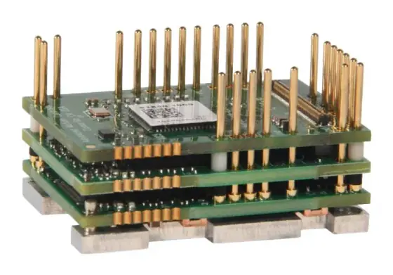
A PCB-mount (embedded) servo drive is the power stage, current loop, position and velocity loops and communication interface of a servo drive, built as a module that sits on your own board. It lets a 48 V robot joint, an AGV wheel or a surgical tool carry its drive inside the mechanism, with no panel and no long motor cables.
In exchange, you take on part of the drive design: board, cooling, bus capacitance and EMC. Select one in this order:
- Motor and feedback type the drive must run.
- Bus voltage and supply: battery, DC supply or both.
- Continuous (RMS) and peak current over the real duty cycle.
- Thermal path: baseplate, heatsink, board copper, airflow, ambient.
- Form factor: plug-in core module, PCB-mount board with connectors, or connectorised micro drive.
- Feedback and communication interfaces.
- Regeneration, protection and safety (STO).
- Carrier board design and EMC.
For panel drives on AC supplies, see how to select a servo drive.
Step 1: motor and feedback
Confirm the drive supports your motor: brushless (sinusoidal or trapezoidal commutation), brushed DC, voice coil or linear motor, and its pole count, inductance and resistance. Low-inductance motors, such as slotless or ironless designs, can produce high ripple current at the drive’s PWM frequency. AMC lists a minimum load inductance for each FlexPro model and recommends an external filter where the motor is below it (AMC).
Then confirm the feedback: digital Halls, incremental A/B/Z, BiSS-C, SSI, EnDat, sin/cos or resolver, and whether a second encoder input is needed for a load-side encoder on a geared joint. Novanta’s Everest and Capitan modules, for example, accept dual BiSS-C, which suits joints with both motor-side and output encoders.
Step 2: bus voltage
Embedded drives typically run from about 8 to 90 V DC. Pick the bus voltage from the motor’s required speed (back-EMF at top speed plus the voltage needed to drive current through the winding) and the available supply. Then check margins on both sides. AMC recommends the supply be at least 10% above the system’s voltage requirement and at least 10% below the lower of the drive’s overvoltage trip and shunt turn-on (AMC).
On battery systems, remember the voltage range from fully charged to cut-off, and what happens during regenerative braking with a full battery.
Step 3: current, continuous and peak
From the load torque profile, find the motor current at each phase of the cycle:
I = T / Kt (A), with torque T in Nm and the motor’s torque constant Kt in Nm/A.
Then calculate the RMS current over the cycle:
I(rms) = √( Σ Iₙ² × tₙ / T(cycle) )
Compare:
- I(rms) with the drive’s continuous rating at your ambient temperature and cooling, not the headline figure.
- The highest current with the drive’s peak rating and the time it may be held. Peak currents on embedded drives are often available for only a few seconds.
AMC’s guidance is to calculate motor current for continuous and peak operation, noting peak torque occurs during acceleration, and to size the supply from the point of maximum voltage × current (AMC).
Rule of thumb: keep RMS current at or below about 70 to 80% of the drive’s continuous rating at the worst-case ambient, unless the maker’s derating curves show more headroom for your cooling.
Step 4: thermal design
This is where most embedded drive projects go wrong. A drive’s continuous rating assumes a cooling arrangement, usually a baseplate clamped to a heatsink or structure:
- AMC recommends mounting the baseplate of FlexPro PCB drives to a heatsink for best thermal management, publishes maximum ambient against continuous current curves for each model, and warns that repeated over-temperature events may damage the drive (AMC).
- Ingenia’s Everest NET manual includes a thermal model, current derating and a heatsink calculation section, which is the place to start for those modules (Ingenia).
Estimate the loss from efficiency at your operating point:
P(loss) ≈ P(out) × (1/η − 1)
Check the temperature rise of the baseplate:
ΔT = P(loss) × Rθ (°C), where Rθ is the thermal resistance from baseplate to ambient in °C/W through the heatsink, thermal pad and structure.
Then make sure the ambient plus the rise stays inside the drive’s limit with margin. Inside a sealed robot joint, the “ambient” is the joint’s internal air, which may be well above room temperature because the motor is also heating it.
AMC also advises designing the mounting board itself for a 100 °C ambient with a 10 °C rise, and allowing for cable heating at peak current.
Step 5: form factor
| Format | What it is | When to choose it |
|---|---|---|
| Core or plug-in module | The drive with a board-to-board connector or pins; communication via SPI or a fieldbus PHY on your board | Highest integration, smallest size; you design the power, feedback and comms circuitry |
| PCB-mount board with fieldbus | Module with EtherCAT or CANopen on board, mounted on your carrier | Most common for robot joints and AGVs; less design effort |
| Connectorised micro drive | Small housed drive with connectors | Prototypes, low volumes, or when you do not want a carrier board |
| Development or evaluation board | Drive on a reference carrier | Prototyping and as a reference layout |
Novanta’s Everest, for example, comes as an SPI core module (34.5 × 26 × 10.4 mm), a PCB-mount EtherCAT/CANopen board and a connectorised XCR unit; AMC’s FlexPro range includes PCB, machine-embedded, panel and development-board formats.
Step 6: feedback and communication
- Fieldbus: EtherCAT for multi-axis synchronised systems such as robot arms; CANopen for mobile robots and simpler networks; SPI to a local processor in highly integrated designs; Ethernet/IP or others where the controller needs them.
- Update rates: check the cycle time the controller needs and that the drive supports it.
Step 7: regeneration, protection and STO
Regeneration. Energy returned during deceleration or lowering raises the bus voltage. The capacitor can absorb:
E = ½ × C × (V(max)² − V(nom)²) (J)
If the kinetic or potential energy returned in one stop exceeds this, you need a shunt regulator, a supply or battery that accepts charge, or a lower deceleration rate. AMC notes a shunt regulator is needed where deceleration or downward motion regenerates energy the supply capacitance cannot absorb (AMC).
Protection. Fit fuses or other overcurrent protection in the supply line, reverse-polarity protection on battery systems, and a disconnect in the final product. AMC’s manual specifies overcurrent protection before or after the supply and recommends a Zener clamp for non-battery sources on its low-voltage models.
Safe Torque Off (STO). If the machine’s risk assessment calls for it, choose a drive with STO rated to the level you need. AMC’s FlexPro STO is rated to EN ISO 13849-1 Category 4 / PL e and SIL 3, with both STO inputs required high to enable torque and a monthly check of the monitoring circuit (AMC). Route STO signals on your carrier as the maker’s safety manual specifies.
Step 8: carrier board design and EMC
Guidance drawn from AMC’s FlexPro PCB manual (AMC), which reflects good practice for most embedded drives:
- Design for maximum values. Size traces and plating for the drive’s peak and continuous currents. Use IPC-2152 or your board house’s data for trace current capacity, and use all the power pins provided, joining traces to pins that share current.
- Keep high-current traces short, and keep DC supply traces separate from motor phase traces.
- Bus capacitance close to the drive power pins, plus ceramic or film capacitors for high-frequency filtering. AMC says external bus capacitance is necessary and gives at least 500 µF / 100 V where the supply is switched or the leads are longer than 36 inches.
- Separate power and signal: keep high- and low-power signals apart, and cross them only at right angles.
- Star grounding: no daisy-chained power or DC commons; case grounds to one central point; shields grounded at the mounting card or chassis.
- Shielded, twisted motor and feedback cables, kept apart. AMC’s rule of thumb is 10 cm of separation for every 10 m of cable.
- Ferrite cores and filters on motor and signal leads where needed; AMC names specific cores and filters for its drives.
EMC compliance is demonstrated on the finished product, so plan a pre-compliance test on the first prototype rather than at the end.
Worked example: a 48 V wrist joint on a collaborative robot
Requirement: A cobot wrist joint with a frameless motor (Kt = 0.10 Nm/A) and a strain-wave gear. Bus 48 V DC. The joint’s worst-case cycle, repeated every 2 s, is 0.4 s of acceleration needing 1.6 Nm at the motor, then 1.6 s at 0.4 Nm. Ambient inside the arm up to 50 °C. Motor-side and output-side BiSS-C encoders. EtherCAT to the robot controller. The drive must fit inside a 40 mm diameter housing.
Current:
- Acceleration: I = 1.6 / 0.10 = 16 A for 0.4 s
- Rest of cycle: I = 0.4 / 0.10 = 4 A for 1.6 s
- I(rms) = √((16² × 0.4 + 4² × 1.6) / 2) = √((102.4 + 25.6) / 2) = √64 = 8 A
Candidates:
- Novanta Capitan: 10 A continuous, 20 A peak, 8 to 60 V DC, dual BiSS-C, EtherCAT or CANopen, published at 18 g with a 34.5 × 26 mm core module. Peak 16 A is inside 20 A. RMS 8 A is 80% of 10 A, which is at the limit of the rule of thumb before any derating for 50 °C.
- Novanta Everest: 45 A continuous, 60 A peak, 8 to 72 V DC, dual BiSS-C, published in a 34.5 × 26 mm core module too. Large current headroom in a similar envelope.
Thermal check: electrical output power at 8 A RMS is a few hundred watts at most; at an assumed 98% efficiency, loss is under about 8 W. With the baseplate clamped to the aluminium joint housing, a combined Rθ of 3 °C/W gives a rise of about 24 °C, so the baseplate reaches about 74 °C at 50 °C ambient. Check that against the maker’s derating curve for the chosen module.
Regeneration: the joint decelerates the same inertia it accelerates, so the energy returned per stop is small, but several joints decelerating together in an emergency stop all feed the same 48 V bus. Size bus capacitance and a shared shunt at system level.
Choice: Capitan meets the numbers on paper but with thin thermal margin at 50 °C. If the derating curve confirms at least 9 A continuous at that baseplate temperature, choose it; otherwise move to Everest. Either way, design the carrier with the module’s published footprint, local bus capacitors, short phase traces to the motor, separate routing for the two encoder links and the STO lines brought out to the robot’s safety circuit.
Products in our range to consider
- Novanta Everest servo drives: 8 to 72 V DC, 45 A continuous, 60 A peak, up to 5 kW, as SPI core module, PCB-mount EtherCAT/CANopen board or connectorised XCR unit.
- Novanta Capitan servo drives: 18 g micro drive for 8 to 60 V DC, 10 A continuous and 20 A peak, BiSS-C and SSI feedback, STO SIL 3.
- Novanta Denali servo drives: the smallest drive in the Summit range, 48 V DC, 5 A continuous and 10 A peak, for micro-automation.
- ADVANCED Motion Controls FlexPro: 10 to 90 V DC, up to 100 A continuous and 200 A peak, in PCB, machine-embedded, panel and development-board formats, STO standard.
- Leadshine ELD3 miniature DC servo drives: 76 × 50 × 33.5 mm, 24 to 70 V DC, 50 to 750 W, available without housing, with STO and a second encoder input.
- Kinco OD mini DC servo drives: palm-sized 24 to 60 V DC drives at 5, 10 or 20 A for 50 to 750 W motors, widely used in AGVs.
- Leadshine 2ELD2 two-axis DC servo drives: dual-axis 24 to 70 V DC drive, 20 or 30 A per axis, with STO, where two axes share one unit.
What else the build needs
- Motor matched to the drive’s voltage and current. See servo and stepper motors, frameless torque motors and how to select a frameless torque motor.
- Feedback, often motor-side and output-side encoders on geared joints. See encoders.
- Gearing. See gearboxes and how to select a harmonic actuator.
- Brake with its own driver and supply, if the axis must hold position unpowered.
- Power supply or battery, bus capacitance and shunt, sized at system level.
- Controller on the chosen fieldbus. See motion controllers.
- Slip ring if power and bus cross continuous rotation. See slip rings.
Things that catch engineers out
- Using the headline continuous rating without the derating for real cooling and ambient.
- No heatsink path for the baseplate inside a sealed housing.
- Peak current held too long, beyond the drive’s peak time limit.
- Too little bus capacitance, or capacitors far from the drive.
- Regeneration on a shared bus during emergency stops.
- Low-inductance motors below the drive’s minimum load inductance.
- Thin traces and single power pins that run hot at peak current.
- Encoder and motor phase traces routed together.
- STO wiring not to the safety manual.
Checklist
Send these to our engineers, or enter them in the spec builder:
- Motor type, Kt, resistance, inductance, pole count
- Bus voltage and supply type (battery range, DC supply)
- Torque or current profile over the duty cycle; RMS and peak current
- Peak duration and repetition
- Ambient temperature and cooling available (baseplate, heatsink, airflow)
- Size and mass limits; preferred format (core, PCB board, connectorised)
- Feedback types and number of encoder inputs
- Fieldbus or command interface; cycle time
- Regeneration energy and shared-bus arrangement
- STO and safety level required
- Brake output needed
- Quantities and timing
For the wider family, see our servo drives overview.
Frequently asked questions
What is a PCB-mount servo drive?
It is a servo drive supplied as a module with pins or a board-to-board connector, designed to plug or solder onto your own carrier board instead of being wired into a panel. It suits robot joints, mobile robots, medical devices and other compact low-voltage machines where a panel drive would not fit. You design the board that brings in power, motor phases, feedback, communications and safety signals.
How do I size the current of a PCB-mount servo drive?
Work out the motor current needed at each part of the duty cycle from the torque and the motor's torque constant. Compare the RMS current over the cycle with the drive's continuous rating at your ambient temperature and cooling, and the highest current with the drive's peak rating and its allowed peak duration. Leave margin: continuous ratings usually assume a heatsunk baseplate.
Does a PCB-mount servo drive need a heatsink?
Usually, for its full rating. ADVANCED Motion Controls, for example, recommends mounting the baseplate of its FlexPro PCB drives to a heatsink for best thermal results and publishes maximum ambient against continuous current curves. Small drives can run without one at low current, but the carrier board, enclosure and airflow then become the cooling path, and the continuous rating drops.
What bus capacitance does a PCB-mount servo drive need?
Follow the drive maker's figure, because the module itself carries only a little. AMC states that external bus capacitance is necessary for its FlexPro PCB drives and recommends at least 500 µF rated 100 V across the supply where the source is switched mechanically or the leads exceed 36 inches. Place it close to the drive's power pins and add ceramic or film capacitors for high-frequency filtering.
What happens to regenerated energy on a low-voltage DC servo drive?
When the motor decelerates or lowers a load, it acts as a generator and pushes energy back onto the DC bus. If the bus capacitance cannot absorb it and the supply cannot sink it, the voltage rises until the drive trips on overvoltage. Add capacitance, a shunt regulator that dumps energy into a resistor, or a supply or battery that can accept charge.
Who is responsible for EMC with an embedded servo drive?
The maker of the final product. A PCB-mount drive is a component inside your equipment, and the emissions and immunity of the finished machine depend on your carrier board, cabling, shielding and enclosure. Drive makers give layout and filtering guidance, such as AMC's recommendations on shielded cables, ferrite cores and star grounding, but compliance is demonstrated on the complete product.
Sources
- ADVANCED Motion Controls: FlexPro PCB mount hardware installation manual (MNFPEMIN)
- Ingenia (Novanta): Everest NET product manual, table of contents (thermal model and derating sections)
Figures are summarised from the sources above and from manufacturers' published data on the date shown. Always confirm against the current datasheet for your exact part.