
In short:Put the drive where its heat, wiring and servicing are easiest to manage for your machine. Panel and multi-axis drives in a cabinet suit dynamic, closely coupled axes; PCB-mount modules suit compact low-voltage products built in volume; integrated and decentralised IP65/IP67 drives cut cabinet space and cabling on spread-out modular machines, at the cost of heat and electronics at the motor.
Every servo drive does the same job: it rectifies or takes in DC power, switches it into the motor winding and closes current, velocity and usually position loops on the motor’s feedback. What changes between form factors is where that box of power electronics lives, and therefore who deals with its heat, its wiring, its EMC and its servicing. That is the decision this guide helps with. For sizing the drive itself, see how to select a servo drive.
Servo drive form factors compared
| Form factor | Where it sits | Typical supply | Strengths | Weak points |
|---|---|---|---|---|
| Panel (cabinet) drive | DIN rail or backplate in a sealed cabinet; drive itself usually IP20 | 230 V or 400 V AC; some 24–90 V DC | Finished, approved, easy to swap; heat and EMC handled in one place | Cabinet space and cooling; long motor and feedback cables to every axis |
| Multi-axis drive, common DC bus | Cabinet, two to four axes per housing or modules on a shared bus | 230 V or 400 V AC; 24–70 V DC versions exist | Shared rectifier, bus and braking resistor; energy exchange between axes | One fault can stop several axes; mixed axis sizes waste channels |
| PCB-mount module | On your own carrier board inside the product | Typically 8–90 V DC | Smallest size and lowest cost at volume; drive goes inside the mechanism | You own thermal design, board layout, protection and EMC |
| Integrated (drive-on-motor) | On the back of the motor | Mostly 24–60 V DC; mains versions exist | One unit and one cable per axis; very little cabinet | Drive shares motor heat; harder to service; limited power |
| Decentralised IP65/IP67 drive | On the machine frame near the motor, fed by a hybrid cable | DC from a central supply module | Big reductions in cabinet space and cable; modular machines | Higher unit cost; sealed electronics on the machine; network and supply planning |
| Embedded / custom drive | Built into a product as a bespoke or semi-custom board | Application specific | Exact fit, form and interfaces | Development time, qualification and lifecycle owned by you |
Panel servo drives: the cabinet default
A panel drive is a housed unit with connectors, a heatsink, protection and approvals. It mounts in a control cabinet with the PLC or motion controller, power supply, contactors and safety relays.
Why engineers choose it: it is the fastest to design in. The maker has already done the thermal design, EMC filtering guidance, safety certification and connector choice. If a drive fails, a technician swaps it from the front of the cabinet.
Thermal: all of its losses go into the cabinet. Kollmorgen notes that because heat is generated centrally, centralised systems often need effective cabinet air conditioning, which is a real cost on large machines (Kollmorgen). Size the cabinet cooling from the sum of every drive’s losses at your duty cycle, plus internal braking resistors, and check each drive’s derating above its rated ambient. The switching frequency matters too: Beckhoff states that raising the PWM frequency of its AX5000 drives raises switching losses, so the rated and peak current are reduced (Beckhoff).
EMC: the long motor cable is the main emitter. Longer and screened motor cables have more stray capacitance, which can call for higher-specification mains filters, and the screen must be RF-bonded to the drive’s enclosure or chassis at one end and to the motor terminal box at the other (REO UK). EN 61800-3 sets categories by environment: C1 drives may be used in the first (domestic) environment, C3 drives are intended for the second (industrial) environment only. Check which category the drive meets with your cable length and filter.
Best for: dynamic, closely coupled axes that sit near one another, such as a gantry, a packaging machine’s main axes or a machine tool. Kollmorgen describes centralised drives as still dominant for highly dynamic, precise motion (Kollmorgen).
Multi-axis servo drives with a common DC bus
A multi-axis drive puts two or four inverter stages behind one rectifier and DC bus, or links separate drive modules through a DC bus bar.
The benefit is energy and hardware sharing. Schneider Electric describes how, on a common DC bus, braking energy from one decelerating drive can be used by another, and how several drives can share one external braking resistor if it is properly rated (Schneider Electric). You also save one network connection, one supply connection and panel width per axis.
The catches:
- Worst-case regeneration is an emergency stop, when every axis decelerates together and none is motoring. Size the braking resistor for that.
- Channel ratings are not always equal, so plan which motor goes on which output.
- Safety zoning: if STO is common to all axes on a unit, an STO demand stops all of them.
- Paralleling separate drives on a DC bus has rules on fusing, precharge and drive combinations. Follow the maker’s application note; Schneider says to consult its common DC bus application note before doing so.
See how to select a multi-axis servo drive for the sizing steps.
PCB-mount servo drive modules
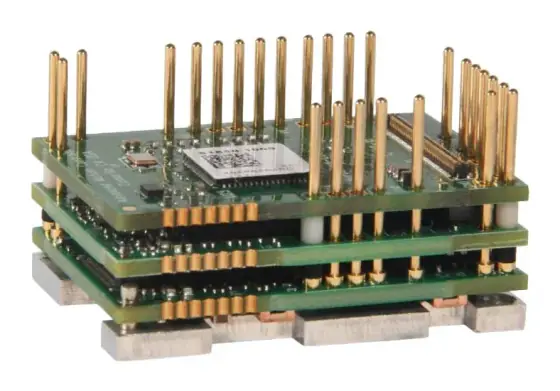
A PCB-mount drive is the power stage, control loops and communication of a drive as a module with pins or a board-to-board connector. It solders or plugs onto your carrier board. It is the form factor of choice for cobot joints, AGV wheels, gimbals, surgical tools and exoskeletons, where a housed drive would not fit or would cost too much at volume.
Thermal: the rated current assumes a cooled baseplate. ADVANCED Motion Controls recommends mounting the baseplate of its FlexPro PCB drives to a heatsink for best thermal results (AMC). Inside a sealed joint, the “ambient” is the air in the joint, which the motor is also heating.
Board and power design: you provide the bus capacitance, protection and connectors. AMC requires at least 500 µF / 100 V of external decoupling capacitance where the supply is switched mechanically or the leads exceed 36 inches (about 0.9 m) (AMC).
EMC: it is your product’s EMC. AMC’s guidance includes connecting case grounds to a single protective earth point in a star arrangement and separating motor power and feedback wires by about 10 cm for every 10 m of cable. Plan a pre-compliance scan on the first prototype.
The full method is in how to select a PCB-mount servo drive.
Integrated servo motors (drive-on-motor)
An integrated servo motor carries its drive in a housing on the back of the motor, so each axis needs only a supply cable and a network cable, sometimes combined. Most are low-voltage DC units of a few hundred watts, used on AGVs, conveyors, format-change and adjustment axes, and lab automation.
Thermal is the limit. The drive’s electronics sit on a component that is itself producing heat. Kollmorgen notes that motor-mounted (“piggyback”) drives derate as ambient temperature rises, so motors may have to be larger than otherwise needed, and rapid acceleration and deceleration are particularly hard to cool (Kollmorgen).
Other trade-offs: you replace motor and drive together on a failure, the unit is longer than the bare motor, and peak power is limited by the space for power electronics. On the plus side, the motor-to-drive cable disappears, which removes one of the main EMC emitters. See how to select an integrated servo motor.
Decentralised (IP65/IP67) servo drives
A decentralised drive is sealed for mounting on the machine, close to its motor, and supplied with DC from a central power module in the cabinet. A single hybrid cable usually carries power and fieldbus from drive to drive in a daisy chain.
Kollmorgen’s AKD-N illustrates the approach: IP67 drives up to 4 kW per axis connected by an 11 mm hybrid cable (A3). In Kollmorgen’s eight-axis metal-forming example, cable fell from 248 m to 34 m (86%), and to 42 m from 372 m (89%) with I/O included. Heat is spread around the machine, so the cabinet’s cooling can shrink or go entirely (Kollmorgen).
Choose it for spatially distributed single axes and modular machines, for example packaging and food lines where each module is built, tested and shipped as a unit. Kollmorgen notes that the slicer axis in its example stayed centralised because a decentralised drive could not meet its power. Mixed architectures work well if both drive types share the same platform and software.
Watch for: the drive’s own IP rating and washdown resistance, connectors that must survive cleaning, the total current along each hybrid-cable string, and service access at height or inside guarding. For hygienic areas see hygienic washdown actuators and IP69K.
Embedded and custom drives
Some products justify a drive designed into the product, either from scratch or as a semi-custom variant of a standard module with a different connector, outline or firmware. It gives an exact fit, but you inherit development, safety certification, qualification and component obsolescence. For most OEMs, a standard PCB-mount module on a custom carrier board gets most of the benefit with far less risk.
Worked example: choosing form factors for a modular tray-packing line
Machine: four identical modules, each 2 m long, each with a 400 W conveyor axis, a 750 W pick-and-place pair working as a gantry, and two 100 W format-change axes. The line runs from 400 V AC. Modules ship separately and are joined on site. The area is cleaned with low-pressure hoses but not high-pressure washdown.
Gantry axes (highly dynamic, closely coupled): keep them on cabinet drives. A two-axis drive on a common DC bus per module shares the braking resistor between the pair, and the gantry pair needs tight synchronisation. Regeneration: size for both axes stopping at once.
Conveyor axis (steady speed, far from the cabinet): a decentralised IP65/IP67 drive near the motor removes a long screened motor cable from each module.
Format-change axes (low power, rarely moving): integrated low-voltage servo motors on a 48 V DC supply are the simplest. Heat is not an issue because they run only at changeover.
Result per module: one small cabinet holding the two-axis drive, a DC supply, the safety relay and network switch, instead of a central cabinet with eight drive channels per module and roughly 2 m to 10 m of motor and feedback cable to each axis. The trade-off is three drive types to stock as spares, which is acceptable if they share a fieldbus and set-up tool.
Checklist
Decide the form factor with these answers, then send them to our engineers or use the spec builder:
- Number of axes, their power and which axes must be tightly synchronised
- Physical layout: distances from cabinet to each motor; modular or single-frame machine
- Supply: AC phases and voltage, or DC bus voltage and battery range
- Duty cycle and regeneration, including emergency stops with all axes braking
- Cabinet space and cooling available; maximum ambient at the motor and in the cabinet
- IP rating needed at the motor and drive; cleaning method and chemicals
- EMC environment (EN 61800-3 category) and motor cable lengths
- Safety functions and whether STO zones are per axis or per group
- Service model: who swaps a failed drive, and how quickly
- Annual volume, which decides whether a PCB-mount module and carrier board pays back
Products in our range to consider
- Leadshine EL7S / EL7 AC servo drives: panel drives from 400 W to 22 kW on 220 V or 400 V supplies, all with STO, in EtherCAT, Modbus/pulse or PROFINET versions.
- Leadshine 4EL7-EC four-axis servo drive: four EtherCAT axes in one housing at 400–1,500 W per axis on 220 V or 400 V, with two STO circuits common to all axes.
- Leadshine 2ELD2 two-axis DC servo drives: dual-axis 24–70 V DC drive at 20 or 30 A rms per axis, said by the maker to save around 30% installed volume against two single drives.
- Novanta Everest servo drives: 8–72 V DC, 45 A continuous and 60 A peak, as an SPI core module, PCB-mount EtherCAT/CANopen board or connectorised unit.
- ADVANCED Motion Controls FlexPro: 10–90 V DC drives up to 100 A continuous in PCB, machine-embedded, panel and development-board formats, with STO as standard.
- ADVANCED Motion Controls DigiFlex Performance: 10–747 V DC and 120–480 V AC drives in PCB, panel and vehicle-mount formats, including an IP65 vehicle-mount version.
- Kinco iSMK integrated DC servo motors: drive built into 40, 60 and 80 mm motors from 100 to 750 W on 24–60 V DC, IP65 as standard with IP67 optional.
- Leadshine iSV2 integrated servo motors: 200–750 W motor-plus-drive units on 24–48 V DC with CANopen or Modbus/pulse control.
Related guides
- How to select a servo drive and how servo drives work
- Servo drives for extreme environments
- Servo vs stepper
- Our servo drives overview and motion controllers
Frequently asked questions
What are the main servo drive form factors?
Five are common. Panel (cabinet) drives are housed IP20 units on a DIN rail or backplate. Multi-axis drives put two to four axes on a shared DC bus in one housing. PCB-mount modules plug or solder onto your own board. Integrated servo motors carry the drive on the motor. Decentralised drives are sealed IP65 or IP67 units mounted on the machine, fed by a hybrid power and network cable.
What is a decentralised servo drive?
It is a servo drive sealed for mounting on the machine frame or motor, not in a cabinet. A central supply module feeds a string of drives through a hybrid cable carrying DC power and the fieldbus. Kollmorgen's AKD-N, for example, is rated IP67 and uses an 11 mm hybrid cable; Kollmorgen reports cable length falling by 86% on an eight-axis machine example.
Are integrated servo motors as good as a separate motor and drive?
For many axes, yes, but the drive shares the motor's heat. Kollmorgen notes that motor-mounted drives derate as ambient rises, so the motor may need to be larger, and very fast acceleration and deceleration is the hardest case to cool. They suit conveyors, format change, AGV wheels and modular stations better than highly dynamic, high-power axes.
When should I use a multi-axis servo drive with a common DC bus?
When several axes of similar size sit in one cabinet and move together. Sharing the DC bus lets a decelerating axis feed an accelerating one and allows one properly rated braking resistor to serve all of them, as Schneider Electric describes for its Lexium 32 drives. It saves panel width and wiring, but a single unit fault can stop every axis on it.
Who is responsible for EMC with a PCB-mount servo drive?
The maker of the finished product. A PCB-mount drive is a component, and emissions and immunity depend on your carrier board, grounding, cabling and enclosure. Manufacturers give layout guidance, such as star grounding to one protective earth point and separating motor and feedback cables, but compliance is demonstrated on the complete machine or device.
Do cabinet servo drives need air conditioning?
Not always, but all their losses end up in the cabinet, so cooling must be sized for the total heat of every drive, braking resistor and power supply inside it. Kollmorgen points out that centralised drives often need effective cabinet cooling, while spreading drives onto the machine reduces or removes it. Check each drive's ambient rating and derating curve.
Sources
- Kollmorgen: Centralised or decentralised drive technology
- A3 (automate.org): Kollmorgen AKD decentralised servo drive system can reduce cabling by more than 80%
- Schneider Electric: Common DC bus (Lexium 32 help)
- ADVANCED Motion Controls: FlexPro PCB mount hardware installation manual
- REO UK: EN 61800-3 EMC for power drive systems
- Beckhoff: AX5000 switching frequency of the IGBT module
Figures are summarised from the sources above and from manufacturers' published data on the date shown. Always confirm against the current datasheet for your exact part.