
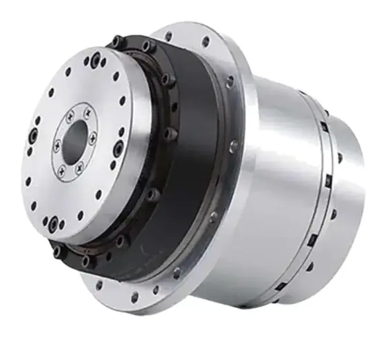
How a strain-wave gear works in one paragraph
A strain-wave gear has three parts. An elliptical wave generator spins inside a thin, flexible, externally toothed cup called the flexspline, and forces it into an ellipse. At the two ends of the ellipse the flexspline teeth engage a rigid internally toothed ring, the circular spline, and at the minor axis they are fully clear. The circular spline has two more teeth than the flexspline, so each time the wave generator turns once, the flexspline ends up two teeth behind where it started relative to the circular spline. A small tooth difference over a large tooth count gives a high ratio in a single stage, and because the teeth are pushed into mesh rather than running with clearance, there is no backlash.
The principle was patented by C. W. Musser in 1957 and first used by United Shoe Machinery in 1960; 80:1 strain-wave gears drove the wheels of the Apollo 15 lunar rover (Wikipedia). Harmonic Drive is a trademark of Harmonic Drive LLC; “strain-wave gear” is the generic term, and it is the one to use in a specification so more than one manufacturer can quote.
This guide explains the mechanism and what it means for a design. For choosing between gear types, see strain-wave vs planetary vs cycloidal.
The three parts: wave generator, flexspline and circular spline
| Part | What it is | What it does | What to watch |
|---|---|---|---|
| Wave generator | A thin-raced ball bearing pressed onto an elliptical plug | Input. Deflects the flexspline into an ellipse and rotates the mesh zone | Its bearing sets the rated life; it must be fitted last and rotated in |
| Flexspline | Thin-walled steel cup (or hat, or flat ring) with external teeth on a slightly smaller pitch diameter | Usually the output. Flexes twice per input turn | Fatigue if overloaded; the main source of torsional compliance |
| Circular spline | Rigid steel ring with internal teeth, two more than the flexspline | Usually fixed to the housing | Concentricity to the flexspline on assembly |
Descriptions follow the Harmonic Drive LLC CSF/CSG catalogue, which describes the wave generator as a thin-raced bearing on an elliptical plug acting as the torque converter.
The flexspline shape gives the main product families:
- Cup type: the flexspline is a deep cup with a closed base for the output flange. Robust, longest axial length.
- Hat (top-hat) type: the cup is turned outwards into a flange, leaving a large open centre for a hollow shaft and cables.
- Flat or pancake type: two circular splines and a short ring flexspline, for the shortest axial length, usually at lower torque for the same diameter.
Each is sold either as a component set (the three parts, built into your housing with your own output bearing) or as a unit with a cross-roller output bearing, seals and grease already fitted.
Strain-wave gear ratio: the maths
Let Z_f be the flexspline tooth count and Z_c the circular spline tooth count, with Z_c − Z_f = 2 on practically all commercial gears.
Circular spline fixed, flexspline output (the standard reduction arrangement in most catalogues):
i = Z_f / (Z_c − Z_f), output rotates opposite to the input
Flexspline fixed, circular spline output:
i = Z_c / (Z_c − Z_f), output rotates in the same direction as the input
Example: Z_f = 200, Z_c = 202. With the circular spline fixed the ratio is 200 / 2 = 100:1, reversed; with the flexspline fixed it is 202 / 2 = 101:1, same direction. Wikipedia’s worked example gives the same 1/100 result for the first case (Wikipedia). Harmonic Drive’s catalogue states the motion plainly: one clockwise turn of the wave generator moves the flexspline two teeth anticlockwise relative to the circular spline (Harmonic Drive LLC).
Practical consequences:
- Ratios run from about 30:1 upwards in one stage. A lower ratio needs fewer teeth on a smaller flexspline, which is why there is no 10:1 strain-wave gear. Harmonic Drive LLC’s CSF range, for example, is listed at 30, 50, 80, 100, 120 and 160:1.
- Direction reversal matters for wiring. If you swap a planetary for a strain-wave gear in the standard arrangement, the output direction flips; change the drive’s direction parameter rather than the motor phases.
- The same gear can step up. Driving the flexspline and taking output from the wave generator is possible in principle, but efficiency is low at high ratio and few manufacturers rate their gears for it. Ask before designing around it.
Why there is no backlash, and what replaces it
The wave generator pushes the flexspline teeth fully into the circular spline at both ends of the major axis, so two zones of teeth carry the load at once. Because the mesh is preloaded, reversing torque does not open a gap. Harmonic Drive states that in the tooth engagement region its gears have no backlash (Harmonic Drive AG).
What you do get are three small, separate errors. For a CSG size 25 at ratio 50 or above, Harmonic Drive publishes (Harmonic Drive AG):
| Figure | Meaning | CSG-25, i ≥ 50 |
|---|---|---|
| Transmission accuracy | Difference between theoretical and actual output angle over one output turn, unloaded | < 1 arcmin |
| Hysteresis loss | Width of the torque–angle loop when torque is cycled from +rated to −rated and back | < 1 arcmin |
| Lost motion | Wind-up measured at about ±4% of rated torque, characterising the low-torque stiffness | < 1 arcmin |
| Repeatability | Half the spread of positions reached repeatedly from one direction | < ±0.1 arcmin |
Read these carefully. “Zero backlash” means no free play, not zero error. Hysteresis comes from friction in the mesh and the flexing steel, so a joint that reverses under load will show a small dead band even with a perfect gear.
Torsional stiffness and wind-up
The flexspline is a thin-walled spring, so a strain-wave gear’s stiffness is modest and non-linear: soft at low torque, stiffer as the teeth bed in. Manufacturers publish three linearised regions. For CSG size 25 at ratio 100 (Harmonic Drive AG):
- K1 = 31 × 10³ Nm/rad from 0 to T1 = 14 Nm
- K2 = 50 × 10³ Nm/rad from 14 to T2 = 48 Nm
- K3 = 57 × 10³ Nm/rad above 48 Nm
At ratio 50 the same size is softer (K1 = 25, K2 = 34, K3 = 44 × 10³ Nm/rad), which is worth knowing when you choose the ratio.
Wind-up is calculated region by region:
- T ≤ T1: φ = T / K1
- T1 < T ≤ T2: φ = T1/K1 + (T − T1)/K2
- T > T2: φ = T1/K1 + (T2 − T1)/K2 + (T − T2)/K3
Multiply radians by 3,438 for arcminutes. For the CSG-25 at ratio 100 that gives:
| Output torque | Wind-up |
|---|---|
| 5 Nm | 0.55 arcmin |
| 14 Nm | 1.55 arcmin |
| 30 Nm | 2.65 arcmin |
| 60 Nm | 4.61 arcmin |
Two design consequences follow. First, a strain-wave joint that carries a steady load (gravity on an arm, wind on a mast) positions to within a fraction of an arcminute repeatably, but its absolute angle shifts with load; if that matters, put an encoder on the output. Second, stiffness sets the axis’s first resonance, roughly f = (1/2π) × √(K / J). The low K1 region is the one a lightly loaded axis lives in, so use K1 for servo tuning estimates.
Speed, efficiency and lubrication
The flexspline flexes twice per input revolution and the wave generator bearing is heavily loaded, so input speed is limited by heat and lubricant, not tooth strength. For size 25, Harmonic Drive gives a maximum input speed of 7,500 rpm on oil or 5,600 rpm on grease, and a maximum average input speed of 5,600 rpm (oil) or 3,500 rpm (grease) (Harmonic Drive AG).
Efficiency is lower than a planetary and varies with speed, temperature, load and ratio, so manufacturers publish curves rather than one number. Read the curve at your speed and coldest operating temperature; no-load running torque rises sharply when the grease is cold.
Grease ranges are narrower than many engineers expect. Harmonic Drive LLC lists its standard SK-1A and SK-2 greases at 0 to +40 °C and 4B No.2 at −10 to +70 °C, and notes that these are grease temperatures in operation, not ambient. Oil-lubricated sets must stay below 90 °C (Harmonic Drive LLC). An outdoor or cold-store axis needs the lubricant agreed with the supplier at the start.
Torque limits, ratcheting and buckling
Strain-wave gears have a hierarchy of torque ratings. For CSG-25 at ratio 100 (Harmonic Drive AG):
| Rating | Value | Use it for |
|---|---|---|
| Rated torque T_N | 87 Nm | Life calculation at 2,000 rpm input |
| Limit for average torque T_A | 140 Nm | Cube-mean torque over the duty cycle |
| Repeatable peak torque T_R | 204 Nm | Normal acceleration and braking peaks |
| Momentary peak torque T_M | 369 Nm | Emergency stops and collisions only |
Above these sit two failure thresholds. Ratcheting torque is where the teeth skip. Harmonic Drive LLC lists 500 Nm for CSF-25 and 650 Nm for CSG-25 at ratio 100, varying with ratio. Ratcheting can leave the flexspline running off-centre, shortens life and can lead to fatigue failure; once teeth have worn, the ratcheting torque falls, so a gear that has ratcheted once is more likely to do it again. Buckling torque, where the flexspline collapses, is higher again: 1,000 Nm for CSF-25 and 1,700 Nm for CSG-25 (Harmonic Drive LLC).
Never design to the ratcheting figure. It is there to tell you how much margin the momentary rating has. The protection is a drive torque limit set so that a jam or collision cannot drive the output above T_M, allowing for the reflected inertia of the motor rotor, which multiplies by the square of the ratio.
Strain-wave gear life
Rated life is set by the wave generator bearing. Harmonic Drive LLC gives L10 = 7,000 h for CSF and 10,000 h for CSG, with L50 five times higher, at rated torque and 2,000 rpm input (Harmonic Drive LLC):
L_h = L_n × (T_r / T_av)³ × (N_r / N_av)
where L_n is the rated life, T_r the rated torque, T_av the cube-mean output torque, N_r = 2,000 rpm and N_av the average input speed. Halving the average torque gives eight times the life.
Assembly decides whether you get that life. Harmonic Drive LLC says the wave generator must be inserted last, after the circular spline and flexspline are installed, while being rotated, and that concentricity should be checked afterwards. An eccentric mesh (which it calls “dedoidal”) causes noise and vibration and can lead to early failure (Harmonic Drive LLC). If you are not set up to control those tolerances, buy a unit or an integrated actuator instead of a component set.
Worked example: pan axis on an outdoor sensor positioner
Requirement: Pan axis for a mast-mounted camera and sensor head. Hollow centre for cables. Wind load gives up to ±30 Nm at the axis; average torque over the duty cycle about 20 Nm. Output speed up to 20 rpm, average input speed about 1,000 rpm. Pointing error budget for the gear ±3 arcmin. Ambient −20 to +45 °C.
Ratio: a frameless motor at up to 2,000 rpm and 20 rpm output gives 100:1, a natural strain-wave ratio. Candidate: CSG size 25, ratio 100.
Torque:
- Average 20 Nm < T_A 140 Nm. Pass.
- Wind peak 30 Nm < T_R 204 Nm. Pass with a large margin, which also helps against gusts and handling knocks below T_M 369 Nm.
Life: L10 = 10,000 × (2,000 / 1,000) × (87 / 20)³ ≈ 1.6 million hours. Bearing fatigue is not the limit here; lubricant and seals are.
Pointing error:
- Wind-up at 30 Nm: 2.65 arcmin (from the table above).
- Hysteresis: under 1 arcmin.
- Transmission accuracy: under 1 arcmin.
A simple sum is up to 4.65 arcmin, over the ±3 arcmin budget. Because wind reverses, the axis also crosses the soft K1 region repeatedly. Options, in order of cost: a larger gear (stiffness rises with size), a higher-torque series at the same envelope, or an absolute encoder on the output so the servo closes the loop on the true pan angle. For a positioner the output encoder is usually the right answer; see absolute vs incremental encoders.
Lubricant: −20 °C is outside the standard grease ranges above. Agree a low-temperature grease and check the efficiency curve and starting torque at −20 °C before sizing the motor.
Choice: a hollow-shaft strain-wave unit at size 25, ratio 100, with a low-temperature grease and a load-side absolute encoder.
Things that catch engineers out
- Treating zero backlash as zero error. Wind-up and hysteresis remain; budget them.
- Using the momentary peak as a design load. It is for collisions; repeated use risks ratcheting.
- Forgetting the reversed output direction in the standard arrangement.
- Running a component set without an output bearing designed for the moment load. The gear carries torque, not your tilting load.
- Assembling the wave generator first, or forcing it in without rotating it.
- Standard grease outdoors or in cold stores.
- Tuning the servo on K3 stiffness when the axis spends its life near zero torque.
Products in our range to consider
These strain-wave gears and actuators are available through our supply network:
- Leaderdrive LCS / LCSG: cup-type strain-wave component sets for building your own joint; ratios 30:1 to 500:1 listed, LCSG around 30% higher torque.
- Leaderdrive LHS / LHSG: hollow-shaft strain-wave units with a large central bore for cables and services.
- Leaderdrive LCD: ultra-flat cup-type strain-wave gear for very short axial lengths.
- Leaderdrive LHD: ultra-flat hollow-shaft strain-wave gear combining low height with a through-bore.
- MAH harmonic servo actuator: strain-wave gear, motor, encoder and brake in one hollow-shaft unit, ratios 51:1 to 161:1, up to 557 Nm rated torque.
- MAT harmonic actuator: large-bore version with a frameless 16-pole motor and bores up to 45 mm.
- MGU harmonic actuator: compact robot-joint actuator with built-in EtherCAT/CANopen drive and dual 20-bit encoders.
For choosing between a gear and an integrated unit, see how to select a harmonic actuator; for the motor inside a joint, see frameless motor sizing for robot joints.
Checklist
Send these to our engineers, or enter them in the spec builder:
- Ratio range, and which element you want fixed (output direction)
- Torque cycle: values and durations, plus repeatable peaks and collision or jam torque
- Average and maximum input speed
- Allowable wind-up at working torque and hysteresis (arcmin)
- Moment, radial and axial loads on the output, and whether you supply the output bearing
- Component set, unit or integrated actuator
- Hollow bore diameter for cables or services
- Envelope limits: outside diameter, axial length, mass
- Operating temperature range and lubricant constraints
- Required life (hours) and duty
- Output encoder needed, and its interface
For the wider family, see our gearboxes overview.
Frequently asked questions
How does a strain-wave gear achieve zero backlash?
The wave generator forces the flexspline into an ellipse so that its teeth are pushed fully into the circular spline at the two ends of the major axis. The teeth are preloaded against each other rather than meshing with clearance, so there is no free play when the direction reverses. What remains is elastic wind-up and a small hysteresis, which Harmonic Drive quotes at under 1 arcmin for its CSG size 25 gears.
How do you calculate the ratio of a strain-wave gear?
With the circular spline fixed, the wave generator as input and the flexspline as output, the ratio is the flexspline tooth count divided by the tooth difference, and the output turns the opposite way to the input. A 200-tooth flexspline in a 202-tooth circular spline gives 200 ÷ 2 = 100:1. If the flexspline is held and the circular spline is the output, the ratio is 202 ÷ 2 = 101:1, in the same direction as the input.
What is ratcheting in a harmonic gear?
Ratcheting is tooth skipping under excessive torque during motion. The flexspline teeth climb over the circular spline teeth, and the flexspline can end up running off-centre. Harmonic Drive warns that this shortens life and can lead to flexspline fatigue failure, and that the ratcheting torque falls once the teeth have worn. Keep collision and jam torques under the momentary peak rating with drive torque limits.
Is a strain-wave gear stiff?
Less stiff than its zero backlash suggests, particularly near zero torque. Stiffness is published in three regions: for a CSG size 25 at ratio 100 it rises from 31 × 10³ Nm/rad below 14 Nm to 57 × 10³ Nm/rad above 48 Nm. At 30 Nm that gear winds up by about 2.6 arcmin. Check wind-up at working torque, not just backlash.
What limits the life of a strain-wave gear?
Rated life is set by the wave generator bearing, so it follows a cube law with torque and is inversely proportional to input speed. Harmonic Drive LLC quotes L10 lives of 7,000 h for CSF and 10,000 h for CSG at rated torque and 2,000 rpm input. In practice, overloads that cause ratcheting, poor assembly concentricity and the grease running outside its temperature range end lives earlier than bearing fatigue.
Are harmonic drives and strain-wave gears the same thing?
Harmonic Drive is a brand name, as noted above, and is often used loosely for the whole technology. Strain-wave gearing is the generic name for the principle, first patented by C. W. Musser in 1957, and several manufacturers now make strain-wave gears. Specify by the generic term plus the figures you need: ratio, rated and peak torque, stiffness, hysteresis, bore and envelope, so that more than one source can quote.
Sources
- Harmonic Drive LLC: CSF and CSG series catalogue
- Harmonic Drive AG: CSG-2A component sets engineering data
- Wikipedia: Strain wave gearing (history and tooth-count example)
Figures are summarised from the sources above and from manufacturers' published data on the date shown. Always confirm against the current datasheet for your exact part.