
In short:Choose iron-core for the most force per size and cost, ironless for zero cogging and the smoothest, fastest-settling motion, and tubular for compact push-pull axes. Then size the forcer on RMS force for heat and peak force for acceleration, use the motor constant to estimate coil losses, and design the bearings, encoder, cable chain and vertical-axis safety around it, because a linear motor holds nothing when the power goes off.
When a linear motor is the right answer
A linear motor drives the load directly, with no screw, belt or gearbox. That removes backlash, wind-up and screw critical speed, so a linear motor axis can run faster, accelerate harder and settle more precisely than a mechanical drive, over almost any stroke. The price is that everything a screw would do for you, holding the load, multiplying force and stiffening the axis, is now your design problem.
Consider a linear motor when the axis needs high speed with high accuracy, very fast settling, long stroke without whip, or many carriages on one track. Stay with a screw or belt actuator when you need high force at low speed, holding with power off, or the lowest cost. The mechanical options are covered in how to select a linear actuator.
The selection sequence
- Choose the motor type: iron-core, ironless, tubular or magnet-free track.
- Define the move profile and moving mass, including an estimate for the coil and carriage.
- Calculate peak and RMS force.
- Choose the coil from continuous and peak force, then check coil losses and temperature using the motor constant and thermal data.
- Choose the track length from stroke plus coil length plus overtravel.
- Choose bearings and structure for payload and any attraction force.
- Choose the encoder and check the drive accepts it.
- Design the cable management, end stops and vertical-axis safety.
- Match the drive.
Iron-core vs ironless vs tubular vs magnet-free track
| Iron-core | Ironless (U-channel) | Tubular | Magnet-free track | |
|---|---|---|---|---|
| Construction | Coils on a laminated stack over one magnet row | Epoxy coil between two magnet rows | Coil around a magnet-filled rod | Magnets in the moving forcer; passive steel track |
| Force density | Highest | Lower | Moderate | Moderate |
| Cogging | Yes, reduced by design | None | Iron-core types yes; ironless none | Yes |
| Attraction force | 5 to 15 times rated force | None | Balanced around the rod | Reduced, depending on design |
| Moving mass | Heavier | Light | Light rod or light coil | Heavier forcer |
| Best for | High force, machine tools, heavy gantries | Smooth velocity, fast settling, metrology, wafer handling | Compact push-pull, pick-and-place, pneumatic replacement | Long, low-cost travel, low EMI near the track |
Iron-core motors are the common choice for general automation; their attraction can preload the bearings for stiffness, but the bearings must carry it, and dual-track designs balance it (Machine Design). Machine Design quotes attraction of 5 to 15 times the rated force for iron-core types, and notes ironless motors are lighter and better for velocity control and high acceleration but less efficient and need more magnets (Machine Design). Parker’s catalogue gives 5 to 13 times rated force for its iron-core range against zero for its ironless range (Parker).
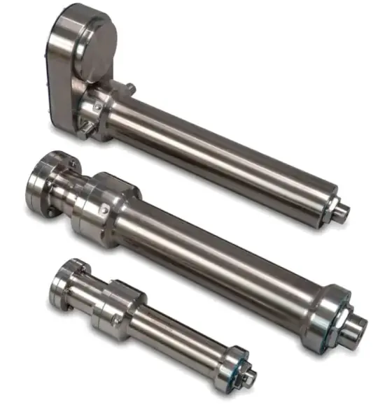
Tubular motors balance attractive forces around the rod, have a non-critical air gap and are used widely as pneumatic replacements in packaging and medical machines (Motion Control Tips).
Magnet-free track designs put the magnets in the moving forcer and use a plain steel track. In our catalogue data this is described as giving low EMI, lower attraction and inexpensive long travel, which suits long gantries and seventh-axis robot tracks.
Force: peak, RMS and the force constant
Size a linear motor exactly as you would a servo, but in newtons rather than newton-metres.
- Peak force: F = m × a + friction + gravity + process force, during the hardest acceleration. Include the coil and carriage in m.
- RMS force: F_rms = √( Σ Fᵢ² × tᵢ / Σ tᵢ ), including dwells where the motor holds a force.
Then compare with the datasheet. Note the conditions: Parker, for example, rates peak force at a 5% duty for 1 s and continuous force at a winding temperature of 100°C (Parker). Other makers rate differently, so compare like with like.
The force constant, Kf (N/A), converts force to current: I = F ÷ Kf. Use it to size the drive’s continuous and peak current.
Motor constant and thermal sizing
The motor constant, Km, is force divided by the square root of input power, in N/√W (Machine Design). It equals the force constant divided by the square root of the winding resistance (Parker). It follows that coil loss is approximately:
P = (F ÷ Km)²
and coil temperature rise is approximately P × R_th, where R_th is the thermal resistance in °C/W. Two consequences:
- Doubling the force quadruples the heat. Aggressive accelerations get expensive thermally.
- Comparing Km is the fairest way to compare motors of similar size. Be careful with thermal data: Machine Design notes some makers test with no heatsinking and others with large heatsinks or forced convection, which inflates the figures.
The heat goes into the coil, and with a moving coil, into the carriage and payload. On precision axes that is a positioning error from thermal expansion. Water-cooled versions are available on high-force iron-core ranges in our catalogue data.
Cogging and force ripple
Cogging is the attraction between the iron stack and individual magnets, felt as a periodic force that varies with position. It disturbs constant-velocity motion and low-speed smoothness. Ironless motors have none; iron-core designs reduce it with skewed magnets or stack shaping, and the drive can compensate some of what remains. If the axis scans, measures or dispenses at constant speed, cogging is often the deciding factor towards ironless.
Encoders
A linear motor axis is only as good as its encoder. Kollmorgen notes linear encoder resolutions of 0.1 µm are common and some reach 20 nm, with accuracy typically 20 µm/m, improvable to under 5 µm/m with slope-error correction (Kollmorgen). Decide:
- Optical or magnetic: optical for resolution and accuracy; magnetic for robustness against dirt and coolant.
- Exposed or enclosed: exposed scales are more accurate but need clean conditions and a controlled read-head gap; enclosed scales tolerate machine-tool environments.
- Incremental or absolute: absolute avoids a homing and commutation-finding move at power-up, which matters on long or crowded axes.
- Interface: analogue sin/cos, digital A/B or serial such as BiSS-C; it must match the drive. Machine Design notes a converter module can bridge mismatches (Machine Design).
- Count rate: maximum speed ÷ resolution must sit inside the drive’s encoder input frequency.
The bearing system and structure must hold both the motor air gap and the read-head gap through the stroke.
Cable management
On a moving-coil motor, the power cable, encoder cable (if the read head moves), Hall sensor and thermal sensor all flex with every stroke. Specify high-flex cables rated for the cable chain’s bend radius and cycle count, keep power and encoder cables separated in the chain, and provide strain relief at the coil. Moving-magnet designs with stationary coils keep the power cables still, which helps on very long or multi-carriage axes; magnet-free track systems still carry their coils, and so their cables, on the moving forcer.
Safety: nothing self-locks
A linear motor has no screw to hold the load. Plan for:
- Vertical axes: Zaber notes a vertical linear motor stage will fall uncontrollably if power is lost while moving, and the motor must carry the full weight continuously, generating heat (Zaber). Use a counterbalance, and a fail-safe safety brake that can stop the load if the drive fails completely (Industrial Production).
- Horizontal axes: on power loss or a fault, the carriage coasts. Fit end-of-travel shock absorbers or bumpers sized for the kinetic energy at full speed, and use the drive’s dynamic braking where available.
- Magnet tracks: strong permanent magnets attract tools and pinch fingers; iron-core coils are drawn onto the track with kilonewtons of force. Use installation fixtures and cover exposed tracks.
- Thermal protection: wire the coil thermistor or thermostat to the drive.
- Functional safety: STO, safe limited speed and brake control belong in the machine’s risk assessment.
Worked example: a fast pick-and-place axis
Application: a horizontal axis moves an 8 kg carriage (coil, bearings, gripper and part) 300 mm in 0.15 s, dwells 0.1 s, returns in 0.15 s, dwells 0.1 s. Cycle 0.5 s. Guide and cable chain friction 15 N. ±5 µm repeatability.
Move profile (1/3 trapezoid):
- v = 1.5 × 0.3 ÷ 0.15 = 3.0 m/s
- a = 3.0 ÷ 0.05 = 60 m/s² (about 6 g)
Forces:
| Segment | Force | Time |
|---|---|---|
| Accelerate | 8 × 60 + 15 = 495 N | 0.05 s |
| Cruise | 15 N | 0.05 s |
| Decelerate | −480 + 15 = −465 N | 0.05 s |
| Dwell | 0 | 0.1 s |
Repeated for the return.
RMS: √( 2 × 0.05 × (495² + 15² + 465²) ÷ 0.5 ) ≈ 304 N. Peak: 495 N.
Coil choice: a coil of at least about 380 N continuous (25% margin on RMS, as a rule of thumb) and comfortably over 495 N peak. In our catalogue data, the largest compact iron-core AJM coils reach 447 N continuous and 1.4 kN peak, and ironless AUM sizes span 3 N to nearly 2 kN continuous.
Iron-core or ironless? The move is point-to-point, so cogging matters less than settling. But an iron-core coil of this rating would pull onto the track with roughly 2 to 6 kN (5 to 13 times rated force), and the guide bearings must carry it. An ironless coil has no attraction and a lighter coil, which lowers the moving mass and therefore the force. The choice comes down to bearing size and cost against magnet cost; get both quoted.
Heat: with an assumed Km of 40 N/√W (use the real datasheet value), coil loss at RMS is (304 ÷ 40)² ≈ 58 W, rising to about 150 W during each acceleration. With an assumed thermal resistance of 0.5°C/W, the RMS rise is around 29°C. If the gripper or part is heat-sensitive, choose the higher-Km coil, not just the higher-force one.
Encoder: ±5 µm repeatability calls for 0.5 µm resolution or finer. At 3 m/s, a 0.1 µm scale produces 30 million counts per second and a 0.5 µm scale 6 million. Check the drive’s input frequency before choosing.
Track: 300 mm stroke + coil length + about 20 mm overtravel each end for bumpers.
Safety: horizontal, so no brake; fit end bumpers sized for ½ × 8 × 3² = 36 J at full speed.
Products in our range to consider
- Akribis AJM: compact iron-core linear motors with high force density, up to 447 N continuous and 1.4 kN peak.
- Akribis AKM: high-force iron-core motors in five widths with optional water cooling, over 6 kN continuous.
- Akribis AQM: narrow, low-cogging iron-core motors for long-stroke, space-constrained axes, up to 506 N continuous.
- Akribis AUM: U-channel ironless motors with zero cogging, from 3 N to nearly 2 kN continuous, up to 5 m/s.
- Akribis AWM: vacuum-compatible ironless motors with high motor constant, up to 769 N continuous.
- MMF4 / MMD magnet-free track linear motor modules: magnets in the forcer and a passive steel track, up to 456 N continuous and 3 m stroke.
- Kinco DD2S linear motor drivers: 230 V AC drives for linear and direct-drive motors, 3–11 A continuous, pulse to 4 MHz or EtherCAT.
- Novanta Everest servo drives: compact 8–72 V DC drive, 45 A continuous, 75 kHz current loop, BiSS-C and SSI feedback.
What else the build needs
- Drive: sized on peak and continuous current from the force constant, with the right encoder input; see servo drives.
- Linear encoder and read head; see encoders and absolute vs incremental encoders.
- Linear guides and structure sized for payload, moments and attraction force.
- Motion controller for multi-axis coordination, gantry yaw control or cam profiles; see motion controllers.
- Cable chain and high-flex cables.
- Counterbalance and safety brake on vertical axes.
- End bumpers and hard stops.
- Cooling for high-duty iron-core axes.
- Compare with screw-driven options in the linear actuators hub.
Things that catch engineers out
- Forgetting the coil and carriage mass when calculating acceleration force.
- Under-sizing guide bearings for iron-core attraction.
- Comparing continuous force ratings measured under different heatsinking.
- Heat in the payload from a moving coil on precision or temperature-sensitive work.
- Encoder count rate beyond the drive’s input at full speed.
- No plan for power loss on vertical axes, or no end bumpers on fast horizontal ones.
- Magnet handling during installation and maintenance.
- Structural resonance: with no compliance in the drive, the frame’s stiffness sets the achievable bandwidth.
Checklist
Send these to our engineers, or enter them in the spec builder:
- Stroke, orientation and number of carriages
- Payload mass and carriage or tooling mass
- Move profile: distances, times, dwells, cycle rate
- Peak and continuous process forces
- Accuracy, repeatability and settling requirements
- Constant-velocity smoothness needed (scanning, dispensing, inspection)
- Environment: cleanroom, vacuum, coolant, dust, temperature
- Heat limits at the payload, and whether water cooling is acceptable
- Supply voltage and drive or fieldbus preference
- Safety: vertical load, power-loss behaviour, end-of-travel protection
Frequently asked questions
What is the difference between iron-core and ironless linear motors?
An iron-core motor winds its coils on a steel lamination stack running over a single row of magnets. It gives the most force per size, but has cogging and a magnetic attraction to the track of several times its rated force. An ironless motor has coils set in epoxy running between two rows of magnets in a U-channel. It has no cogging and no attraction, a lighter moving coil, and smoother motion, at higher magnet cost and lower force density.
What is the motor constant of a linear motor?
The motor constant, Km, is force divided by the square root of the power lost in the coil, in N/√W. It is the force constant divided by the square root of winding resistance. A higher Km means less heat for the same force, so it is the best single figure for comparing motor efficiency. Coil loss at a given force is approximately (F ÷ Km)².
How big is the attraction force in an iron-core linear motor?
Large. Machine Design quotes 5 to 15 times the rated output force, and Parker's catalogue 5 to 13 times. A motor rated at a few hundred newtons can pull its coil onto the track with several kilonewtons, so the linear guides must be sized for it, and installation needs proper tooling. The attraction can be useful as bearing preload. Dual-track designs balance it out.
Do linear motors need a brake on a vertical axis?
Yes, or a counterbalance and a safety brake. A linear motor has no screw or gearbox, so nothing self-locks: Zaber notes a vertical linear motor stage will fall if power is lost while it is moving. The motor must also carry the full weight continuously, which generates heat. Use a counterbalance (pneumatic, magnetic, spring or counterweight) plus a fail-safe linear brake or rod clamp.
What encoder resolution do linear motors need?
Linear motors are commonly paired with linear encoders resolving 0.1 µm, with some reaching 20 nm, according to Kollmorgen. Accuracy is a separate figure, typically around 20 µm per metre uncorrected. Check that the drive can accept the encoder's count rate at full speed: at 3 m/s with 0.1 µm resolution the encoder produces 30 million counts per second.
When should I use a tubular linear motor?
Use a tubular motor for compact push-pull or pick-and-place axes and as a high-performance replacement for pneumatic cylinders, especially in packaging and medical equipment. The magnets sit inside a sealed rod and the coil surrounds them, so attractive forces balance out and the air gap is not critical. Strokes are limited by rod length and stiffness, and you still need external guidance for side loads.
Sources
- Machine Design: How linear motors measure up
- Machine Design: Five steps to linear motor integration
- Parker: I-Force ironless and RIPPED ironcore linear motors catalogue
- Kollmorgen: How to select direct drive linear actuators
- Kollmorgen: Feedback devices, exploring linear, rotary and sine encoders
- Motion Control Tips: When do tubular linear motors outperform traditional designs?
- Zaber: Magnetic counterbalances for vertical applications
- Industrial Production: Safety brakes, no free fall on linearly moving axes
Figures are summarised from the sources above and from manufacturers' published data on the date shown. Always confirm against the current datasheet for your exact part.