
In short:Decide first whether the load is pushed along its own guide (rod actuator) or carried by the actuator (rodless), then pick screw drive for force and accuracy or belt for long, fast strokes. Check side load, duty cycle and environment before force and speed, because those three rule out most of the wrong options; then size the motor and screw with the numbers.
The selection sequence
Selecting a linear actuator is mostly about ruling things out. Work through the decisions in this order:
- Is the load guided already, or must the actuator carry it? That decides rod vs rodless.
- What side loads and moments are there? That may force a guided or rodless design.
- How long, how fast, how hard? Stroke, speed and thrust decide screw vs belt and ball vs roller screw.
- What duty cycle? That rules DC actuators in or out.
- What environment? Washdown, dust and temperature decide sealing, materials and motor.
- Holding and back-driving: brake or self-locking screw.
- Motor and control: DC, stepper, servo or integrated.
- Then size it with the force and torque maths in how to size a linear actuator.
Rod vs rodless actuators
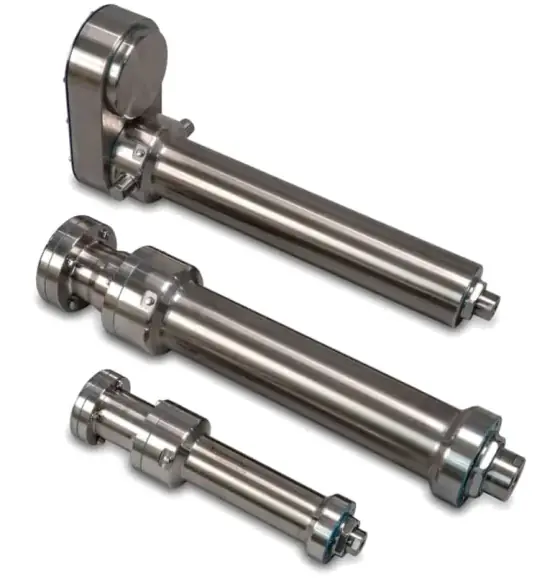
Rod actuators (electric cylinders) extend a thrust rod from the body. They suit pushing, pressing, clamping, lifting on external guides and replacing pneumatic or hydraulic cylinders. They are compact across their width, seal well around the rod, and can be pivot-mounted with clevises and trunnions.
Rodless actuators move a carriage along the body on integral bearings. Tolomatic notes they carry the load themselves, removing separate guidance, and keep the stroke within the body for a smaller footprint (Tolomatic). They suit transfer axes, gantries, XYZ systems and anything where the load sits on top of the axis.
| Need | Usually points to |
|---|---|
| Push or press along a guided path | Rod actuator |
| Pivoting motion (lever, flap, hatch) | Rod actuator with clevis mounts |
| Carry a payload on the axis | Rodless with profiled rail or bearing carriage |
| Long stroke, more than about 1.5 m | Rodless (belt for very long) |
| Offset loads but rod form needed | Guided rod actuator with integral guide rods |
| Washdown, smooth exterior | Hygienic stainless rod actuator |
Side loads and guidance
Rod actuators are built for axial load. Tolomatic warns that a rod-style actuator is vulnerable to damage and wear if the extended rod sees even moderate side loads, which come mainly from misalignment and wear the front bearing and nut (Tolomatic). Side load gets worse as the rod extends, because the bending lever grows.
Three ways to handle it:
- External guidance: run the load on its own linear guides and connect the rod through a floating joint. IAI recommends a floating joint to absorb small parallelism errors, and checking that sliding resistance stays uniform across the stroke by watching motor current (IAI).
- Guided rod actuator: integral guide rods and a tooling plate take side and offset loads.
- Rodless actuator: the carriage bearings take the load. Check every moment (pitch, roll, yaw) from the load offset, including dynamic moments at acceleration and deceleration; published moment ratings are usually for one moment acting alone (Tolomatic).
Screw vs belt drive
Tolomatic’s comparison for rodless actuators sets out the trade-off (Tolomatic); the figures are their typical ranges, converted to metric:
| Screw drive | Timing belt drive | |
|---|---|---|
| Stroke | Short to medium, up to about 3 m | Long, about 5 m standard and longer |
| Speed | Up to about 1.3–1.5 m/s | Up to about 5 m/s |
| Thrust | Up to about 12 kN | Up to about 1.45 kN |
| Repeatability | About ±0.013 mm | About ±0.05 mm |
| Lead accuracy | About 0.25–0.33 mm/m (rolled ball nut) | About 0.8–1.25 mm/m |
| Efficiency | About 90% ball nut, 60% composite nut | About 90% |
| Back-driving | Ball nuts usually back-drive; lead nuts under 50% efficiency generally do not | Always back-drives |
Long screws are limited by critical speed (screw whip), so for long and fast strokes the belt wins. For vertical belt axes, a brake is essential.
Ball screw vs roller screw (and lead screw)
- Lead (acme) screws: cheap, quiet, often self-locking, but low efficiency and limited life and duty. Common in DC actuators and linear steppers.
- Ball screws: the default for servo and stepper actuators: high efficiency, predictable life, moderate force.
- Planetary roller screws: more contact points for much higher force, shock resistance and life in the same envelope; the usual choice for replacing hydraulics.
The detailed comparison is in ball screw vs roller screw, and hydraulic replacement in hydraulic to electric actuators.
Integrated motor actuators
An integrated motor actuator builds the servo motor into the actuator body, driving the screw directly. Compared with a bolt-on motor, you lose the coupling or belt, the overall length drops, and there are fewer joints to seal. That makes them attractive for food and beverage, filling and high-duty pressing. The trade-offs: the motor is not independently replaceable, it must be paired with a compatible drive, and heat from the motor sits inside the actuator.
If you use a separate motor, choose inline mounting for best efficiency and dynamic response, or reverse-parallel to shorten the package and allow a rear clevis (Tolomatic).
Hygienic and washdown actuators
For food, dairy and pharmaceutical splash zones, look for:
- Stainless construction, often 316, with a smooth exterior and no pockets that trap product
- IP69K for high-pressure, high-temperature washdown, and IP67 at minimum where water is present
- Food-grade lubricant and seals rated for your cleaning chemicals
- A stainless or hygienic motor, or an integrated stainless actuator
Hygienic electric cylinders are offered with IP69K ratings and, as an option, 3-A and USDA approvals for meat, poultry and dairy food zones (Design World). Remember that IP ratings describe static tests; Tolomatic notes vibration, heat, cold and motion also affect sealing (Tolomatic).
DC actuators and linear steppers
12/24 V DC actuators with acme screws and internal gearboxes are cheap, self-contained and often self-locking. They suit adjustment, lifting and occasional positioning, but in our catalogue data they are typically rated at 10% duty (for example 1 minute on, 9 minutes off). They are the wrong choice for a production axis that cycles continuously.
Linear steppers build a lead screw into a hybrid stepper (Helix Linear):
- Captive: integral anti-rotation spline; the shaft extends like a small cylinder. Short strokes.
- Non-captive: the screw passes through the motor and the load must stop it turning; stroke limited only by screw length.
- External: a rotating screw with a travelling nut, for driving slides and stages.
They give fine travel per step in a tiny package, for pumps, valves, lab automation and medical devices, but are open loop and light duty unless you add an encoder.
Duty cycle
Duty cycle is the proportion of time the actuator is moving: 2 s moving and 2 s stopped is 50%. Tolomatic warns that underestimating it causes overheating and premature failure, and overestimating it oversizes the axis (Tolomatic). Servo-driven actuators do not have a fixed duty limit; they are sized on RMS torque.
Worked example: a hygienic carton pusher
Application: a pusher plate transfers a row of five cartons (8 kg each) sideways off a conveyor in a meat packing hall. Stroke 300 mm, out in 1.0 s, back in 1.0 s, 2 s dwell. Carton friction on the belt μ ≈ 0.3. Pusher plate and bracket 4 kg. Daily hot caustic washdown. 230 V AC available.
Step 1, rod or rodless: the cartons are not carried; they are pushed. A rod actuator.
Step 2, side load: the plate is 600 mm wide and the cartons do not load it evenly, so there will be an offset force and moment. The rod must not take that. Use two hygienic external guide rods carrying the plate, with the actuator rod connected through a floating joint.
Step 3, environment: washdown rules out standard aluminium actuators. We need stainless, IP69K and a stainless or integrated motor.
Step 4, duty: 1 s out and 1 s back in a 4 s cycle is 50% duty, all day. A 10% duty DC actuator is ruled out. Servo drive.
Step 5, force and speed (from the sizing guide):
- Peak speed (1/3 trapezoid): v = 1.5 × 0.3 ÷ 1.0 = 0.45 m/s; a = 0.45 ÷ 0.333 ≈ 1.35 m/s²
- Friction: 40 × 9.81 × 0.3 ≈ 118 N
- Acceleration: 44 kg × 1.35 ≈ 59 N
- Peak ≈ 177 N; returning empty, about 6 N plus guide friction
Step 6, lead and motor: with a 3,000 rpm servo, lead_min = 450 × 60 ÷ 3,000 = 9 mm, so a 10 mm lead (motor at 2,700 rpm). Torque ≈ 177 × 0.010 ÷ (2π × 0.9) ≈ 0.31 Nm plus rotary inertia, so a small servo.
Step 7, holding: horizontal, with no holding force needed in the dwell, so no brake.
Candidates: a stainless rod actuator such as the Tolomatic ERD in its SS2 stainless form (IP69K, leads including 10 mm, up to 2,224 N and about 1 m/s in our catalogue data) with a hygienic servo, or the Tolomatic IMA-S integrated stainless actuator (IP69K, speed up to about 500 mm/s in our catalogue data), which removes the separate motor from the washdown zone.
What changes the answer: if the stroke rises to 1 m in the same time, peak speed reaches 1.5 m/s and the hygienic rod options above run out of speed; a sealed belt or a guarded conventional axis becomes the conversation. If the cartons were carried rather than pushed, a rodless axis would carry the load directly.
Products in our range to consider
- Tolomatic ERD: economical stainless-tube rod actuator up to 2,224 N and 610 mm stroke, with IP69K stainless options.
- Tolomatic RSA-HT: high-thrust rod actuator with roller-screw options, reaching 58 kN.
- Tolomatic RSH: all-316 stainless hygienic rod actuator, IP69K, ball or roller screw up to 35.3 kN.
- Tolomatic IMA: integrated servo motor rod actuator up to 30.6 kN peak and 13.1 kN continuous.
- Tolomatic B3S: screw-driven rodless actuator with integral bearing guidance, up to about 12 kN thrust and 4.5 m stroke.
- Tolomatic B3W: wide-belt rodless actuator for strokes up to 14.6 m at up to 5 m/s.
- LE Ballscrew Linear Actuator: ball screw linear module with built-in guide rail, ±0.02 mm repeatability and up to 1,450 mm stroke.
- GT44 Linear Actuator: 12/24 V DC worm-gear acme actuator rated 6,000 N push at 10% duty.
- Dings External Linear Stepper Actuator: hybrid stepper with external lead screw and travelling nut, NEMA 6 to 34, up to 2,400 N.
- Dings Captive Linear Stepper Actuator: hybrid stepper with integral anti-rotation shaft, up to 63.5 mm stroke.
What else the build needs
- Motor: servo or stepper sized from the force and lead; see servo and stepper motors and servo vs stepper.
- Drive and controller: matched to the motor and fieldbus; see servo drives and motion controllers.
- Gearing or belt reduction: for reverse-parallel mounts or to fix inertia ratio; see gearboxes.
- Brake: on any vertical or inclined axis, and every vertical belt axis.
- Feedback: motor encoder for most axes; a linear scale for full closed loop; see encoders.
- Guidance: external linear guides and a floating joint for rod actuators.
- Sensors: home and limit switches or encoder-based homing.
- Cabling: continuous-flex cable and a cable chain for moving motors.
- Power supply: 12/24 V DC for DC actuators, or the servo drive’s supply.
Things that catch engineers out
- Hanging a payload off the rod of a rod actuator.
- Ignoring dynamic moments on rodless carriages at acceleration and deceleration.
- Assuming the stroke is the body length. Dead length adds to every actuator.
- Using a 10% duty DC actuator on a continuously cycling axis.
- Mounting a belt axis vertically without a brake.
- Specifying IP67 for high-pressure washdown, where IP69K and hygienic design are needed.
- Copying fluid-power safety factors. Tolomatic notes the habit of a 2:1 margin inflates the cost of electric actuators; size to the real profile instead (Tolomatic).
- Long screws at high speed, which run into critical speed.
Checklist
Send these to our engineers, or enter them in the spec builder:
- What the actuator does: push, pull, lift, carry, press, clamp
- Load mass, how it is guided, and any offsets or side loads
- Orientation: horizontal, vertical or incline
- Stroke, move times, dwells and cycle rate
- Peak and continuous force, and where in the stroke they act
- Accuracy and repeatability
- Holding requirement with power off
- Environment: washdown, IP rating, temperature, dust, food contact
- Motor preference and supply voltage, drive and fieldbus
- Mounting style, envelope and connection to the load
Frequently asked questions
What is the difference between a rod and a rodless linear actuator?
A rod actuator extends a thrust rod out of its body, like a pneumatic cylinder, and is built to push or pull along its axis; the load needs its own guidance. A rodless actuator moves a carriage along the body on integral bearings, so it can carry the load and its moments directly, and its stroke sits inside its own length. Rod styles suit pressing and pushing; rodless styles suit transfer and positioning.
Should I choose a belt-driven or screw-driven linear actuator?
Choose a screw for high thrust, better accuracy and repeatability, and vertical axes that must resist back-driving. Choose a belt for long strokes and high speed with lower thrust. Tolomatic's comparison gives screw-driven rodless units up to about 12 kN thrust and ±0.013 mm repeatability, against belt units up to about 1.45 kN and 5 m/s with ±0.05 mm repeatability.
Can a rod-style electric actuator take side loads?
Only very small ones. Tolomatic warns that a rod-style actuator is vulnerable to damage and wear if the extended rod sees even moderate side loads, which wear the front bearing and can damage the nut. Guide the load externally with a floating joint, choose a guided-rod version with integral guide rods, or use a rodless actuator that carries the load on its own bearings.
What duty cycle can an electric linear actuator run?
It depends on the type. Many 12 or 24 V DC actuators with acme screws are rated at around 10% duty, for example one minute on and nine minutes off, because their motors have no thermal management. Servo- or stepper-driven ball screw and belt actuators are sized on RMS torque and are commonly rated up to 100% duty. Calculate duty from real on and off times.
When should I use a linear stepper motor instead of a linear actuator?
Use a linear stepper for short-stroke, light-load, open-loop positioning in compact equipment such as valves, pumps, lab instruments and medical devices. The lead screw is part of the motor, so it is small and simple, with fine travel per step. Captive versions have built-in anti-rotation; non-captive and external versions need the load to stop the screw or nut turning.
What is an integrated motor linear actuator?
It is a rod actuator with the servo motor built around or in line with the screw in one housing, so there is no separate motor, coupling or belt. It is shorter than an actuator with a bolt-on motor, has fewer parts to seal, and suits food and high-duty applications. The trade-off is that the motor cannot be swapped independently, and you must use a compatible drive.
Sources
- Tolomatic: Screw vs belt actuators (9900-9210)
- Tolomatic: Tips for selecting electric rodless actuators (9900-9201)
- Tolomatic: How to specify an electric actuator (9900-4032)
- IAI: Caution when using a guide with a rod type actuator
- Helix Linear: Captive vs non-captive linear stepper motor actuators
- Design World: Hygienic stainless steel electric cylinders (Tolomatic)
Figures are summarised from the sources above and from manufacturers' published data on the date shown. Always confirm against the current datasheet for your exact part.