
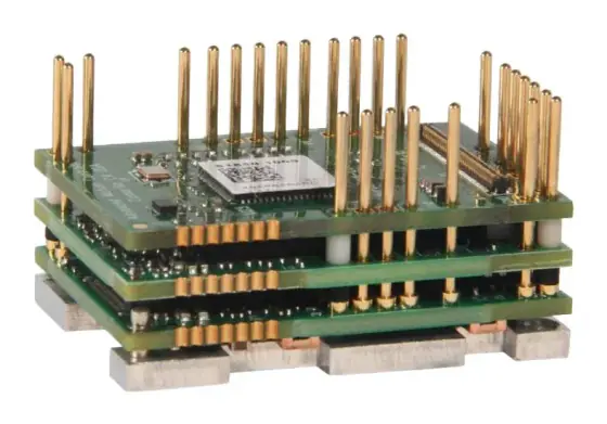
In short:A servo drive converts supply power into a DC bus, then switches that bus into the motor's phases with pulse-width modulation so the winding current follows a command. Nested control loops, current inside velocity inside position, compare the command with encoder feedback thousands of times a second; field-oriented control turns the current loop into direct torque control, while braking energy and Safe Torque Off are handled by the bus circuit and the gate drivers.
A servo drive is the power amplifier and the fast half of the control system for a servo axis. Your controller decides where the axis should be; the drive makes the motor get there by regulating current in the winding, using feedback from the motor’s encoder. Knowing what happens inside it makes datasheets easier to compare, commissioning faster and faults easier to diagnose. If you are choosing a drive, pair this with how to select a servo drive.
Inside a servo drive: the building blocks
| Block | What it does | What to look for on a datasheet |
|---|---|---|
| Rectifier and DC bus | Converts AC mains to DC (or accepts DC directly) and stores energy in bus capacitors | Supply range, bus voltage, inrush limiting |
| Power stage (inverter) | Six transistors (IGBTs or MOSFETs) switch the bus onto the three motor phases | Continuous and peak current, PWM frequency, derating |
| Gate drivers | Turn the transistors on and off; STO acts here | STO rating (SIL/PL), safety manual |
| Current sensing | Measures phase currents for the current loop and protection | Current resolution, overcurrent protection |
| Feedback interface | Reads the encoder or resolver for rotor angle, speed and position | Supported protocols, second encoder input |
| Control processor | Runs commutation, FOC and the current, velocity and position loops | Loop update rates, bandwidth, filters |
| Communication | Receives commands: fieldbus, pulse/direction, analogue | EtherCAT, CANopen, PROFINET, EtherNet/IP; operating modes |
| Braking circuit | Switches a resistor across the bus when it rises too high | Internal resistor rating, external resistor minimum |
The power stage and PWM
The motor needs a sinusoidal current in each phase whose amplitude and frequency change constantly. The drive cannot produce that by dissipating voltage in linear transistors at any useful efficiency, so it switches them fully on and off at a fixed frequency and varies the on-time: pulse-width modulation. The winding’s inductance smooths the pulses into a current that follows the average voltage.
Switching frequency is a trade-off. A higher PWM frequency reduces current ripple and audible noise, and helps low-inductance motors, but every switching event costs energy. Beckhoff, for example, offers 4, 8 and 16 kHz on its AX5000 drives and states that the higher switching losses at higher frequency reduce the drive’s rated and peak current (Beckhoff). Low-voltage MOSFET drives often switch much faster: Novanta’s Capitan micro drive, for example, is published with a PWM range of 20 to 200 kHz. If you change the PWM frequency, recheck the drive’s current rating.
Low-inductance motors (slotless, ironless, many frameless designs) see larger ripple at a given PWM frequency. Some drive makers specify a minimum load inductance and recommend a series inductor below it.
Commutation and field-oriented control
A brushless motor has no commutator, so the drive must energise the phases in step with the rotor’s angle. Two methods dominate:
- Trapezoidal (block) commutation uses Hall sensors to switch current between pairs of phases every 60 electrical degrees. It is simple, but produces torque ripple at each step.
- Sinusoidal commutation with field-oriented control (FOC) is the norm in servo drives.
FOC works in the rotor’s frame of reference. The Clarke transform converts the three phase currents into a two-axis stationary frame; the Park transform rotates that frame with the rotor, giving two quasi-DC quantities. Id sets field strength and is held at zero in normal operation; Iq is directly proportional to torque (Synapticon). Two PI controllers regulate Id and Iq, and inverse transforms turn their outputs back into three PWM duty cycles.
The result is maximum torque per ampere, smooth torque at low speed and fast torque response across the speed range. The cost is that FOC needs the rotor angle in real time, which is why the drive must read your encoder protocol, and why a commutation offset error shows up as lost torque and heating.
Many drives also implement field weakening: deliberately driving negative Id at high speed to counter back-EMF and extend the speed range, at the cost of extra current.
Current, velocity and position loops
Servo drives use a cascade of loops, each nested inside the next:
- Current (torque) loop, innermost: makes the measured Iq follow the torque command.
- Velocity loop: compares commanded and measured speed and outputs a torque command.
- Position loop, outermost: compares commanded and measured position and outputs a velocity command.
Each inner loop must be clearly faster than the one around it, or it cannot support it. The rule of thumb is that the velocity loop’s bandwidth should be five to ten times the position loop’s, and the current loop’s five to ten times the velocity loop’s (Motion Control Tips). Raising an outer loop’s bandwidth therefore raises the demands on every loop inside it. Update rates reflect this: Synapticon’s SOMANET torque loop runs at 16 kHz (Synapticon), and Novanta’s Everest drives are published with a 75 kHz current loop.
Where the loops run depends on the operating mode. With a fieldbus using CiA 402 cyclic synchronous position (CSP), the controller generates the trajectory and sends a target position every bus cycle; the drive closes position, velocity and current loops and interpolates between setpoints when its loops run faster than the bus. In cyclic synchronous velocity (CSV) the controller closes the position loop; in cyclic synchronous torque (CST) the drive closes only the torque loop (Motion Control Tips). See EtherCAT vs PROFINET vs EtherNet/IP for the network side.
Feedback: what the drive needs from the encoder
The drive uses feedback for three things: rotor angle for commutation, speed for the velocity loop and position for the position loop. Resolution and noise matter most for the velocity loop, because speed is calculated by differentiating position; a coarse encoder makes a noisy velocity signal and limits the gain you can use.
- Incremental encoders with Halls are economical but need homing after power-up.
- Serial absolute encoders (BiSS-C, EnDat, Tamagawa and others) give position at power-up and high resolution.
- Resolvers are robust in heat, shock and contamination, at lower accuracy.
- Dual-loop control closes the position loop on a load-side encoder or linear scale while commutating on the motor encoder.
See absolute vs incremental encoders and how to select an encoder.
Servo tuning basics
Tuning sets the loop gains so the axis is stiff, responsive and stable. Modern drives auto-tune, but you should know what they are doing:
- Get inertia right. The drive’s gains scale with total inertia at the motor. A wrong load inertia figure gives sluggish or unstable loops.
- Tune from the inside out. Motion Control Tips gives a practical order: raise the velocity proportional gain to just before overshoot, raise the velocity integral gain until 5 to 15% overshoot, then raise the position gain slowly to just before overshoot, and retest across the speed range (Motion Control Tips).
- Use feedforward. Velocity and acceleration feedforward cut following error without high feedback gains. The same source notes that adding velocity feedforward may require lowering the position gain, which reduces stiffness.
- Filter resonances. Belts, long shafts and couplings create resonances. Notch and low-pass filters on the torque command let you keep gains up; vibration-suppression features handle low-frequency sway at the end of a move.
If a well-tuned axis still rings, the cause is usually mechanical compliance or a high load-to-motor inertia ratio: fix it with a stiffer coupling or a gearbox. See harmonic vs planetary vs cycloidal.
Regeneration and braking resistors
When the motor slows a load or lowers one, it becomes a generator. Current flows back through the transistors’ diodes into the DC bus and charges the capacitors. If the energy is more than they can take, the bus reaches the overvoltage threshold and the drive trips. Kollmorgen describes the fix: add a regen resistor that converts excess energy into heat, sized and fused according to the drive’s installation manual, or share one resistor across several drives on a common bus (Kollmorgen).
Inside the drive, a comparator watches bus voltage and switches a braking transistor on above a threshold, connecting the resistor across the bus until the voltage falls. Its continuous power rating, not just its resistance, decides whether it survives your duty cycle.
Safe Torque Off inside the drive
Safe Torque Off is the basic drive safety function in IEC 61800-5-2. It prevents the drive from supplying torque-producing current by blocking the power transistors’ gate signals in hardware, using two independent channels that must both be active for torque to be possible. The STO input is active-low, so a broken cable gives the safe state. STO is a stop category 0: the motor coasts (Synapticon).
Because STO removes torque, it does not hold a vertical axis. Safe Brake Control engages the holding brake first and applies STO after a set delay; SS1 brings the axis to a controlled stop and then applies STO. Higher functions such as SLS and SOS need a drive with an extended safety module and safe feedback.
Worked example: why a rotary table trips on overvoltage
Axis: an indexing table with total inertia at the motor of 0.004 kg·m², driven at 3,000 rpm and stopped in 0.1 s. A 230 V drive with a DC bus of about 325 V, bus capacitance 470 µF and an overvoltage trip at 400 V (read the real figures from the drive manual).
Kinetic energy at speed: ω = 3,000 × 2π ÷ 60 ≈ 314 rad/s. E = ½ × J × ω² = ½ × 0.004 × 314² ≈ 197 J.
What the bus can absorb: E = ½ × C × (V_trip² − V_bus²) = ½ × 470 × 10⁻⁶ × (400² − 325²) ≈ 12.8 J.
Even allowing 20–30% for friction and copper losses, about 140–160 J must go somewhere. Without a braking resistor, the drive trips on the first stop.
Braking power: 150 J in 0.1 s is a peak of about 1.5 kW. If the table stops every 2 s, average power is 150 ÷ 2 = 75 W. Choose a resistor at or above the drive’s minimum resistance, rated for at least the average with margin for its temperature rise, and confirm the peak against the drive’s braking transistor rating.
Control-loop check on the same axis: if the position loop is to settle the index in a few tens of milliseconds, it needs a bandwidth of perhaps 30 Hz. By the five-to-ten rule, the velocity loop then needs roughly 150–300 Hz and the current loop above 1 kHz. Most modern drives meet that easily; a belt or long shaft in the drive train may not, which is when notch filters or a stiffer coupling come in.
Checklist
Use this to read a servo drive datasheet, or send it to our engineers with the spec builder:
- Supply and DC bus voltage, and the motor winding they suit
- Continuous and peak current (rms or peak), and the peak’s duration
- PWM frequency options and the derating at each
- Motor types and commutation supported; minimum load inductance
- Feedback protocols, resolution, second encoder input
- Current, velocity and position loop update rates or bandwidths
- Operating modes on the fieldbus (CSP, CSV, CST, profile modes)
- Tuning tools: auto-tune, notch filters, feedforward, scope
- Braking circuit: internal resistor power, external minimum resistance, shared bus
- STO rating (SIL/PL, category), brake output, SBC and SS1 support
Products in our range to consider
- Leadshine EL8 AC servo drives: 220 V AC drives from 400 W to 2 kW with 3.5 kHz bandwidth, STO SIL 3 and dual-encoder full closed-loop control.
- Kinco JD2 AC servo drives: 50 W to 7.5 kW, a wide choice of encoder protocols plus a second encoder input, and STO SIL 3 / PL e on every model.
- Kinco FD5P PRO AC servo drives: 220 or 380 V drives to 7.5 kW with 17/23-bit absolute feedback; mid and high power models have a built-in brake resistor.
- Leadshine ELD2 DC servo drives: 24–70 V DC, 5 to 60 A rms and up to 180 A peak, driving brushless, brushed and PMSM motors.
- Novanta Everest servo drives: 8–72 V DC, 45 A continuous and 60 A peak, with a 75 kHz current loop.
- ADVANCED Motion Controls DigiFlex Performance: drives for almost any motor and feedback type, 10–747 V DC and 120–480 V AC, up to 150 A continuous.
Related guides
- Servo drive form factors explained
- Servo drives for extreme environments
- Servo vs stepper and how to select a servo motor
- Our servo drives overview
Frequently asked questions
What does a servo drive actually do?
It makes the motor produce exactly the torque, speed or position the controller asks for. The drive measures motor current and position, compares them with the command, and adjusts the voltage it switches onto each motor phase to correct the error. Most drives close current, velocity and position loops themselves; on a fieldbus the controller sends a new setpoint every cycle.
What is field-oriented control in a servo drive?
Field-oriented control (FOC) transforms the three measured phase currents into two quantities aligned with the rotor: Id, which sets field strength, and Iq, which is proportional to torque. The drive holds Id at zero in normal operation and regulates Iq, giving maximum torque per ampere and smooth torque at low speed. It needs the rotor angle in real time from an encoder or resolver.
How fast are the control loops in a servo drive?
Each loop is faster than the one around it. A common rule is that the velocity loop's bandwidth should be five to ten times the position loop's, and the current loop's five to ten times the velocity loop's. The current loop is often updated at tens of kilohertz: Synapticon quotes 16 kHz for its torque loop, and Novanta's Everest a 75 kHz current loop.
Why does a servo drive need a braking resistor?
When the motor decelerates a load or lowers one, it works as a generator and feeds energy back onto the drive's DC bus. The bus capacitors can store only a little before the voltage reaches the overvoltage trip. A braking resistor, switched on by the drive, turns the excess into heat. Shared DC buses and regenerative supplies are the alternatives.
What does Safe Torque Off do inside the drive?
STO blocks the gate signals of the power transistors in hardware, through two independent channels, so the drive cannot send torque-producing current to the motor. The motor then coasts, a stop category 0. The input is active-low, so a broken wire also gives the safe state. STO is not a brake: vertical axes need a holding brake as well.
How do I tune a servo drive?
Start with auto-tuning and an accurate load inertia, then refine. Tune the innermost loop you are responsible for first: the velocity loop's proportional gain up to just before overshoot, then its integral gain until 5 to 15% overshoot, then the position gain. Add feedforward to cut following error, and notch filters where the mechanics resonate.
Sources
- Synapticon Motion Control Academy: Field-oriented control (FOC) explained
- Motion Control Tips: Servo motor current, velocity and position loop bandwidths
- Motion Control Tips: How are servo system velocity control loops tuned?
- Motion Control Tips: What is cyclic synchronous control (position, velocity, torque)?
- Beckhoff: AX5000 switching frequency of the IGBT module
- Kollmorgen: Bus overvoltage faults and how to resist them
- Synapticon Motion Control Academy: Safe Torque Off (STO) and Safe Brake Control (SBC)
Figures are summarised from the sources above and from manufacturers' published data on the date shown. Always confirm against the current datasheet for your exact part.