
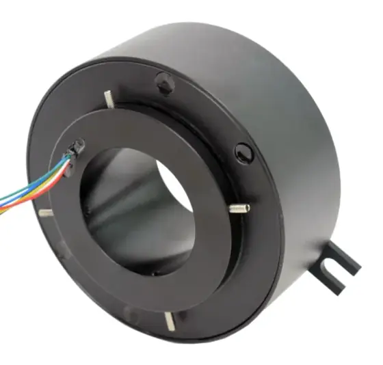
In short:A slip ring passes power and signals from a stationary frame to a rotating one through conductive rings that turn against stationary brushes, so cables never wind up. Contact material, ring diameter and speed decide its electrical noise and wear life; contactless versions replace the sliding contact with capacitive, inductive or optical coupling for data or modest power.
What a slip ring does
A slip ring (also called a rotary electrical joint, collector or swivel) lets power, signals and data cross from a stationary structure to one that rotates continuously, without a cable that winds up and breaks. If an axis turns more than about one revolution, or turns indefinitely, you need either a slip ring or a cable carrier that limits the rotation. Turntables, robot wrists, CCTV pan heads, process drums, wind turbine hubs, cable reels and radar pedestals all rely on them.
Every contact slip ring has the same three parts:
- Rings on the rotor: conductive bands, one per circuit, separated by insulating barriers.
- Brushes on the stator: spring-loaded contacts that press on the rings and slide as the rotor turns.
- A housing with bearings that keeps the rotor concentric with the brushes, plus leads or connectors on both sides.
Each ring and its brush (or brushes) make one circuit. Moog describes the contact surfaces as almost always noble-metal alloys, typically gold or silver (Moog FAQ).
The rings can be stacked along the axis like a drum, which is the common arrangement, or laid out concentrically on a flat disc (a platter or pancake ring) when axial length is tight (Moog, How to specify). For the practical differences between the formats, see capsule vs through-bore vs pancake slip rings.
Slip ring contact materials compared
The contact pair decides noise, current capacity, wear debris and maintenance. Moog’s wind turbine white paper sets out the three main systems clearly (Moog white paper):
| Contact system | Construction | Strengths | Watch for |
|---|---|---|---|
| Gold-on-gold (monofilament) | Gold alloy wire brushes, usually in pairs, on hard gold rings | Very low, stable contact resistance; low torque; ideal for signals and data | About 1 A per brush, so high current needs brushes in parallel; periodic cleaning on long-life designs |
| Silver-graphite / metal-graphite (carbon) | Sintered brushes, typically 60–80% graphite and 20–40% silver or copper, on silver or copper alloy rings | High current; graphite is self-lubricating; tolerant and serviceable | Sheds conductive debris by design, so the ring needs barriers and creep distance; noisier than noble metal |
| Fibre brush | Bundles of fine precious-metal wires on noble-metal plated rings | Many contact points, light force, no contact lubricant, negligible debris, long life | Higher unit cost; quality depends heavily on the maker |
The white paper gives a sense of scale for each. Its metal-graphite design needs no maintenance for the first 50 million revolutions or five years, then a vacuum clean every two years. Its fibre brush test ran 124 million revolutions without reaching end of life, with contact noise below 20 mΩ throughout. Monofilament designs were expected to exceed 100 million revolutions with cleaning after five years.
Fibre brush makers make bolder claims. MOFLON says a fibre brush runs at about 20% of the spring pressure of an equivalent carbon brush and has contact noise typically ten times lower than silver-graphite (MOFLON). Treat such figures as the maker’s own and ask for test data at your speed and current.
“Carbon brush” in slip ring catalogues usually means a metal-graphite brush. You meet copper-graphite power rings on high-current collectors for cranes, cable reels and ship machinery, often with precious-metal rings alongside for the signal circuits in the same unit.
Electrical noise, contact resistance and what it means for signals
Contact noise is the variation in resistance as a brush slides. Moog quotes about 10 to 20 mΩ for typical designs and says the resulting voltage variation is below the noise floor of most common signals (Moog FAQ). The arithmetic is Ohm’s law: the white paper notes that 50 mΩ of variation at a constant 100 mA gives about 5 mV peak to peak.
That tells you where noise matters:
- Power circuits: irrelevant. 20 mΩ on a 10 A feed is 0.2 V of ripple on a 400 V supply.
- Digital I/O, 4–20 mA loops, fieldbus: usually fine. A current loop is immune to series resistance within its compliance voltage.
- Low-level analogue: a strain-gauge bridge giving 2 mV/V on 10 V excitation has only 20 mV full scale. Here specify low-noise contacts, multiple brushes per ring, and preferably amplify or digitise the signal on the rotor.
- Thermocouples: the ring and brush materials form extra junctions. Convert to a robust signal before the slip ring where you can.
Shielding also matters. Run screens through their own ring, keep power and signal rings apart with spare or earthed rings between them, and specify crosstalk isolation where it matters; Moog’s specification sheet asks for it in dB (Moog, How to specify).
Slip ring speed and life: why diameter matters
Wear depends on sliding distance, not revolutions alone. Surface speed is v = π × D × n / 60, with D the ring diameter in metres and n in rpm. A 30 mm capsule ring at 300 rpm slides at 0.47 m/s; a 300 mm pancake or large-bore ring at the same speed slides at 4.7 m/s, ten times further per revolution. Moog notes that speed and diameter together set the internal design and material choice.
Typical figures from Moog (FAQ, How to specify):
- Almost any slip ring runs to 100 rpm; the typical limit is about 250 to 1,000 rpm depending on size, materials and environment.
- Special designs run above 20,000 rpm, for example on jet engine test rigs. Moog’s product guide lists fibre brush capsules to 10,000 rpm without cooling (Moog product guide).
- Life: tens of millions of revolutions for typical instrumentation rings, 100+ million for wind turbine designs.
Convert your duty to revolutions before comparing: rpm × 60 × operating hours per year. Oscillating motion (a gimbal sweeping ±90°) wears a short arc repeatedly and should be declared, because it is a different wear pattern from continuous rotation.
Power, signal and data paths through a slip ring
A single slip ring usually carries several kinds of circuit, and each is built differently:
- Power rings are wider, sometimes with several brushes in parallel, and spaced for voltage. Moog says power is limited only by physical size, with units above 25 kV and above 1,000 A (Moog FAQ). Rate only the circuits that need high current; if three of 20 need 10 A, do not rate all 20 that way.
- Signal rings are narrow, gold-on-gold or fibre brush, and grouped with screens.
- Data rings are designed as controlled-impedance pairs. Moog says most smaller slip rings conduct signals to 50 Mbit/s satisfactorily, special designs pass 500 Mbit/s or more, and its rings are optimised for Gigabit Ethernet and HD video. See Ethernet through slip rings for cable categories, connectors and testing.
Protect the power side: Moog identifies voltage spikes as a major cause of slip ring failure, with spikes of ten or more times operating voltage on some supplies, and recommends surge protection on every power supply (Moog, How to specify). Servo motor power through a slip ring also needs attention to the drive’s PWM edges and screen continuity.
Contactless transmission: capacitive, inductive and optical
Where wear, debris or data rate rule out sliding contacts, the joint can be bridged without touching:
- Capacitive coupling sends data across a small gap between rotating and stationary electrodes. Moog’s Rotocap units carry 100 Mbit/s up to 2.5 Gbit/s and list PROFINET, EtherCAT, Sercos III and Powerlink (Moog product guide). SPINNER quotes up to 1 Gbit/s, a 100 Mbit/s real-time mode for deterministic fieldbuses and a bit error rate below 10⁻¹² (SPINNER).
- Inductive coupling transfers power through a rotary transformer. SPINNER offers 24 V DC at up to 300 W; MESA’s inductive modules work across gaps up to 10 mm, rated to 350 W but more typically 5 to 50 W (Power & Motion).
- Optical transmission uses a fibre optic rotary joint for very high bandwidth and immunity to electrical interference.
The practical limit is power: contactless systems carry data and control power well, but kilowatt motor feeds are still usually done with rings and brushes. Hybrid assemblies combining contact power rings with a contactless data channel are common. The trade-offs are covered in contact vs contactless slip rings.
Rotary unions as companions
A rotary union passes air, vacuum, coolant, oil or hydraulic fluid through sealed rotating channels. It is often built into the same assembly as the slip ring, with the media down the centre and the electrical rings around it. Moog’s product guide lists units at 415 bar and states that unions rated to 1,000 bar are available (Moog product guide). Decide early which media need a bore, because the union sets the minimum through-hole for the electrical rings. Our rotary union selection guide covers seal types and leakage.
Worked example: a rotary indexing table
Duty: an assembly turntable rotating continuously in one direction at 20 rpm for 16 hours a day, 250 days a year. On the table: a 750 W servo axis (400 V AC, 3 A), a 24 V DC brake, 16 digital I/O over an EtherCAT I/O module, a load cell at 2 mV/V, and compressed air for grippers. A 25 mm air line runs up the centre.
Circuits:
- Servo power: 3 phases plus protective earth, rated 5 A each at 400 V AC
- Brake: 2 circuits at 1 A
- 24 V supply for I/O module: 2 circuits at 4 A, plus 2 spare
- EtherCAT (100BASE-TX): 2 pairs plus screen, Ethernet-rated rings
- Load cell: 4 wires plus screen, low-noise rings, or amplify on the table and send the value over EtherCAT instead
- Total: about 20 circuits with spares
Life: 20 rpm × 60 × 16 × 250 = 4.8 million revolutions a year. A ring rated for 20 million revolutions lasts roughly four years before service; a fibre brush design rated beyond 100 million covers the machine’s life.
Noise check: if the load cell signal goes through the rings, 20 mV full scale against 10 to 20 mΩ variation on the excitation leads is workable only with six-wire sensing. Putting the amplifier on the table removes the problem and frees four rings.
Format: the 25 mm air line needs a bore, so a through-bore slip ring with a single-channel rotary union in the centre, or a combined electrical and pneumatic unit.
Products in our range to consider
These are available through our supply network:
- AR/BR/CR Series capsule slip rings: gold-to-gold capsules from 5.5 mm OD with up to 76 circuits.
- ER Series through-bore slip ring: bores from 12.7 to 100 mm, up to 15 A per circuit, published life of 20 million revolutions.
- BHR Series frameless carbon brush slip ring: copper-graphite power rings to 500 A per circuit with precious-metal signal rings.
- Ethernet slip ring: 100M or Gigabit Ethernet channels alongside power and signal circuits.
- FR Series fibre optic rotary joint: up to 50 optical channels, to 2,000 rpm.
- QR Series pneumatic/hydraulic rotary joint: up to 20 air or fluid channels, optionally with electrical circuits.
- Pneumatic/Hydraulic Integrated Electrical Slip Ring: up to 16 media channels at 10 MPa with up to 48 circuits.
Checklist
Send these to our engineers, or enter them in the spec builder:
- Circuit list: function, normal and peak current, working voltage, and which are screened
- Data: protocol and rate (EtherCAT, PROFINET, Gigabit Ethernet, HD-SDI, CAN), and whether real-time
- Low-level analogue signals, and whether they can be amplified on the rotor
- Speed (maximum and continuous), direction, and whether motion is continuous or oscillating
- Required life in revolutions or years at your duty
- Bore needed for shafts, cables or media, and the maximum envelope (length, diameter)
- Fluids: medium, pressure, flow and number of channels
- Environment: temperature, IP rating, vibration and shock, washdown or salt spray
- Lead lengths, connectors and exit direction on rotor and stator
- Whether contactless data or power would be acceptable
For the full method, read how to specify a slip ring and how to select a slip ring type, or browse the slip rings hub.
Frequently asked questions
How does a slip ring work?
A slip ring has a stack of conductive rings on the rotating part and a set of stationary brushes that press on them. Each ring and its brush form one circuit, so current or a signal flows across the joint while it turns continuously in either direction. Insulating barriers separate the rings, bearings keep rotor and stator concentric, and leads or connectors take each circuit out on both sides.
What are slip ring contacts made of?
Signal and low-power circuits almost always use noble-metal alloys, typically gold or silver, which resist surface films and keep contact resistance low. High-current rings often use metal-graphite brushes, which Moog describes as typically 60 to 80% graphite and 20 to 40% silver or copper, on silver or copper alloy rings. Fibre brushes use bundles of fine precious-metal wires on plated rings.
How long does a slip ring last?
It depends on contact type, speed, diameter and environment. Moog gives typical instrumentation slip rings a life in the tens of millions of revolutions and wind turbine designs more than 100 million. Life is quoted in revolutions, not hours, so convert your duty: a ring turning 60 rpm around the clock does about 31.5 million revolutions a year.
What causes electrical noise in a slip ring?
Noise is the small variation in contact resistance as the brush slides over the ring. Moog quotes about 10 to 20 milliohms for typical designs, which is below the noise floor of most signals. It matters for low-level analogue circuits such as strain gauges and thermocouples, where low-noise contact materials, more brushes per ring and amplifying the signal on the rotor all help.
Can a slip ring transmit Ethernet?
Yes. Contact slip rings designed for it carry 100 Mbit/s and Gigabit Ethernet using controlled-impedance ring pairs, and Moog says smaller rings can handle serial data to about 1.25 Gbit/s. For higher rates, or where contact wear on the data path is unacceptable, use a capacitive contactless data link or a fibre optic rotary joint alongside the power rings.
What is the difference between a slip ring and a rotary union?
A slip ring transfers electrical power and signals across rotation; a rotary union transfers fluids such as air, vacuum, coolant or hydraulic oil through sealed rotating channels. They are often combined in one assembly, with the fluid channels down the centre and the electrical rings around them, so a turntable or drum can receive power, data and media from one rotating interface.
Sources
- Moog: Slip ring frequently asked questions
- Moog: High reliability slip ring design for wind turbines (white paper)
- Moog: Slip ring product guide
- Moog: How to specify a slip ring
- MOFLON: Fibre brush slip rings
- SPINNER: Contactless rotary joints for industry
- Power & Motion: Virtual slip rings transmit power or signals across air gaps
Figures are summarised from the sources above and from manufacturers' published data on the date shown. Always confirm against the current datasheet for your exact part.