
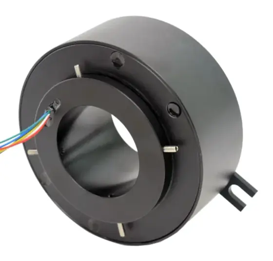
In short:Count the optical channels you really need, match the fibre type and wavelengths to your transceivers, then check the joint's worst-case insertion loss, including its variation over a full turn, against your optical power budget with margin to spare. If power and signals must also cross the rotation, specify a hybrid unit with the joint on the axis and an electrical slip ring around it.
The decisions, in order
A fibre optic rotary joint (FORJ) passes light from a fibre on the rotating side of a machine to a fibre on the stationary side. Engineers choose one when copper data rings run out of bandwidth, when the signal must be immune to electrical noise, or when the system already runs on fibre and converting to copper and back would add cost and failure points. Typical uses are radar and sensor pedestals, electro-optical turrets, ROV and cable-reel systems, wind turbines and high-resolution video on rotating platforms.
Select one in this order:
- Optical channels: how many independent fibres must cross the rotation, and whether multiplexing can reduce that number.
- Fibre type and core size on each channel: single-mode or multimode, and which multimode grade.
- Wavelengths your transceivers use.
- Insertion loss, wow and return loss against your optical power budget.
- Mechanical fit: speed, envelope, connectors or pigtails, and the rest of the rotating interface.
- Hybrid needs: power, signals, fluid or RF in the same assembly.
- Environment: temperature, sealing, shock and vibration, pressure for subsea.
If you are still choosing between slip ring types, start with our slip ring selection guide; this page assumes you need light across the joint.
Step 1: single-channel or multi-channel
Single-channel joints couple two fibres sitting on the rotation axis. With nothing off-axis, the optics are simple, compact and fast, and losses are low. Princetel gives typical insertion loss of about 0.5 dB for single-channel units and about 3 dB for dual and multi-channel units (Princetel).
Multi-channel joints have to keep several off-axis fibres aligned while the rotor turns. The classic method is a derotating prism driven at half the rotor speed; a patent for a single-mode multi-channel joint describes exactly this, with a Dove prism as one option (US 5,157,745). That mechanism is why multi-channel joints are larger, lower in speed and higher in loss. Moog’s published range runs from 2-channel models to a 52-channel single-mode model, with insertion losses from under 3.5 dB to 6.5 dB, and most of its larger multi-channel models carry a lower speed rating than its small two-channel units (Moog).
Reduce the channel count before you buy channels. A single single-mode fibre can carry several data streams on different wavelengths using coarse or dense wavelength-division multiplexing (CWDM or DWDM). Princetel notes that a multiplexer and a single-channel joint can cost less than an n-channel joint. You also get the lower loss and higher speed of the single-channel design. The trade-off is the multiplexers at each end, and that all streams depend on one channel, so specify a spare where availability matters.
Count spares. Fibre channels cannot be added to a joint later. One spare channel on a multi-channel joint is cheap insurance against a damaged pigtail or a future sensor.
Step 2: single-mode or multimode
Match the joint to the fibre in the link. Do not mix types across the joint.
- Single-mode (9/125 µm): the core is about 9 µm. Used for long links and most new high-bandwidth systems at 1310 and 1550 nm.
- Multimode (50/125 µm OM2 to OM4, or 62.5/125 µm OM1): larger cores, cheaper short-reach transceivers, typically at 850 or 1300 nm.
Macartney’s FORJ Model 300, for example, offers 9/125 µm single-mode, 50/125 µm (OM2) and 62.5/125 µm (OM1) multimode, with OM3/OM4 optional, and allows single-mode and multimode channels in the same unit (Macartney).
A mismatch in multimode grade (50 µm fibre feeding a 62.5 µm channel, or the reverse) adds loss at the interface, so state the exact grade, not just “multimode”.
Step 3: wavelength
State every wavelength the channel will carry. Joints are tested at specific wavelengths and loss can differ between them. Princetel lists 850, 1310 and 1550 nm as the common wavelengths and considers a 0.5 to 1.0 dB difference in insertion loss between 1310 and 1550 nm generally acceptable (Princetel).
Wavelength matters more when you multiplex. A CWDM link may use channels spread over hundreds of nanometres, so ask for loss across the whole band. Macartney, for instance, specifies its single-mode channels over 1270 to 1625 nm and gives different wow limits for testing at one wavelength or at both 1310 and 1550 nm.
Step 4: insertion loss, wow, return loss and the link budget
This is where most FORJ problems are decided. Four figures matter:
- Insertion loss: the light lost through the joint. Use the maximum over a full rotation, not the typical value.
- Wow (insertion loss variation): how much the loss changes as the joint turns. Princetel quotes under ±0.25 dB for single-channel units (Princetel); Macartney specifies ≤1.5 dB for multimode channels and up to 3.0 dB for its largest single-mode unit tested at two wavelengths (Macartney).
- Return loss: how much light the joint reflects back towards the transmitter. Princetel notes that reflection causes power jitter in sensitive lasers such as DFB types and cites 40 dB as a common requirement for single-mode passive components. Macartney’s multi-channel unit is ≥18 dB as standard. If your laser or sensor is reflection-sensitive, specify return loss explicitly.
- Crosstalk between channels on multi-channel units: Princetel gives typically better than 60 dB.
How to check the link budget
The optical power budget is the transmitter’s minimum launch power minus the receiver’s minimum acceptable input power. Every connector, splice, length of fibre and the rotary joint must fit inside it, with margin.
Budget = P(tx, min) − P(rx, min)
Loss = FORJ maximum loss + (connector pairs × loss per pair) + splices + fibre attenuation
Margin = Budget − Loss
For connector pairs, the Fluke Networks loss-budget guidance uses 0.75 dB per mated pair and 0.3 dB per splice (Fluke Networks). As a rule of thumb, keep at least 3 dB of margin for ageing, dirty connectors and repairs.
Step 5: speed, envelope and terminations
- Speed: multi-channel joints are often rated around 100 rpm; single-channel and small multi-channel designs go much faster. The FR Series in our range is rated to 2,000 rpm.
- Life: published figures are typically in revolutions. Macartney quotes more than 100 million revolutions for its Model 300, the same figure given for the FR Series.
- Pigtails or receptacles: Princetel recommends pigtailed joints for more repeatable performance, because a faulty pigtail connector can be re-terminated, whereas damage to a receptacle can be permanent. Specify connector type (FC, ST, SC, LC), polish and pigtail length on both rotor and stator.
- Mounting: the joint needs a drive mechanism (a fork, pin or flexible coupling) that turns the rotor without side loading it. Do not let the joint carry structural load or act as a bearing.
Step 6: hybrid joints with electrical slip rings
Most rotating systems need power and control signals as well as optical data. The usual arrangement is the FORJ on the rotation axis with an electrical slip ring around it or stacked with it, in one housing. Hybrids can also include fluid passages for air or coolant, or RF channels for antennas.
Points to settle early:
- The optical channel takes the axis. Any other passage must go around it, which sets the bore of the electrical rings.
- Power circuits close to the fibre do not affect the light, but they do generate heat and brush wear debris; the supplier must seal the optical section from it.
- Speed is set by the slowest element. A hybrid with a multi-channel FORJ is usually limited by the joint.
Our fibre optic rotary joint type page and Ethernet through slip rings guide cover when copper Ethernet rings are enough and when fibre is the better route.
Step 7: environment
List operating and storage temperature, IP rating, shock and vibration, and humidity. Fibre joints are sensitive to condensation and contamination on the optical faces, so sealed housings matter outdoors. For subsea work, joints can be fluid-filled and pressure-compensated: Macartney rates such versions of its Model 300 to 10,000 psi (about 690 bar). See our subsea ROV and AUV page for the wider system.
Worked example: Gigabit links on a rotating sensor platform
Requirement: A sensor platform rotating continuously at 60 rpm sends two independent Gigabit Ethernet streams (camera and radar data) to the base, about 80 m of fibre in total. It also needs 24 V power and a CAN bus across the rotation. The customer’s switches use 1000BASE-LX transceivers at 1310 nm on single-mode fibre.
Budget: Cisco’s data sheet gives a transmit power range of −3 to −9.5 dBm and a receive range of −3 to −20 dBm for its 1000BASE-LX/LH module (Cisco). Worst-case budget = −9.5 − (−20) = 10.5 dB.
Option A: two-channel single-mode FORJ.
| Item | Loss |
|---|---|
| FORJ maximum insertion loss (assume 4.0 dB over full rotation) | 4.0 dB |
| Four mated connector pairs at 0.75 dB | 3.0 dB |
| 80 m single-mode fibre at 1310 nm | under 0.1 dB |
| Total | about 7.1 dB |
Margin = 10.5 − 7.1 = 3.4 dB. Acceptable, but with little room for an extra patch panel.
Option B: one single-mode channel with CWDM. Two wavelengths share one channel through a single-channel joint. With a single-channel joint loss of about 0.5 dB typical (as a working assumption, allow about 1.5 dB maximum until you have the datasheet) plus two multiplexers, each adding its own loss from its datasheet, the link usually has more margin than Option A and the joint can be smaller and faster. The cost is two multiplexers and the need for CWDM transceivers.
Hybrid: either way, the 24 V supply and CAN bus go through an electrical slip ring built around the optical channel, so the specification sent to the supplier lists both.
Choice: for a two-stream system that may grow, Option A with a third spare channel is simpler to commission. The specification states: three single-mode channels, 1310 nm, maximum insertion loss ≤4 dB over 360°, return loss stated, FC/APC pigtails 1 m each side, 60 rpm continuous, plus four 24 V power circuits and one shielded twisted pair for CAN.
Products in our range to consider
- FR Series fibre optic rotary joint: 1 to 50 single-mode or multimode channels, 650 to 1650 nm, insertion loss 4 dB maximum, to 2,000 rpm.
- Fibre optic integrated electrical slip ring: hybrid unit combining fibre channels with up to 70 power and signal circuits at up to 30 A, used on electro-optical pods.
- Multi-channel slip ring: high-circuit-count rings, up to 500 circuits, with fibre optic and RF channel options.
- ER Series through-bore slip ring: through-bore electrical rings with bores from 12.7 to 100 mm, suitable for fitting around a central optical channel.
- Ethernet slip ring: copper 100M or Gigabit channels with power, for systems where fibre is not needed.
- RR Series RF rotary joint: one to five RF channels, single-channel models to 50 GHz, often combined with optical and electrical channels on antennas.
What else the build needs
- Electrical slip ring for power and control. See slip rings and how to specify a slip ring.
- Drive and motor for the rotating axis. See servo drives and servo and stepper motors, or frameless torque motors for direct-drive pedestals.
- Feedback for the axis position, often a hollow-shaft encoder that leaves the bore free. See encoders.
- Gearing if the axis is driven through a slewing ring or gearbox. See gearboxes.
- Optical transceivers, multiplexers and fibre with matched type, grade and connectors.
- Controller to manage cable wrap, homing and any spin limits. See motion controllers.
Things that catch engineers out
- Budgeting with typical loss. Use the maximum over 360° at your wavelengths.
- Forgetting the connectors. Two pigtails and patch panels can add as much loss as the joint.
- Dirty end faces. Contamination at the joint’s connectors is a common cause of high loss; inspect and clean before blaming the joint.
- Mismatched multimode grade across the joint.
- Return loss ignored with reflection-sensitive lasers.
- Side load on the rotor from a rigid drive pin or misaligned mounting.
- No spare channel on a multi-channel joint.
- Speed limit set by the FORJ in a hybrid, discovered after the motor was sized.
Checklist
Send these to our engineers, or enter them in the spec builder:
- Number of optical channels, plus spares
- Fibre type and grade per channel (9/125, 50/125 OM2–OM4, 62.5/125)
- Wavelengths per channel, including any CWDM or DWDM band
- Transceiver models or optical power budget
- Maximum insertion loss, wow and return loss required
- Connector type and polish (FC, ST, SC, LC; PC or APC), pigtail lengths
- Speed (rpm) and duty, continuous or oscillating
- Electrical circuits: number, current, voltage, signal types
- Fluid or RF passages, if any
- Envelope: OD, length, bore, mounting and drive arrangement
- Temperature, IP rating, shock, vibration; depth or pressure for subsea
- Quantities and timing
For the wider family, see our slip rings overview.
Frequently asked questions
What is a fibre optic rotary joint?
A fibre optic rotary joint (FORJ) is the optical equivalent of a slip ring. It passes light between a fibre on a rotating part and a fibre on a stationary part, so data can cross continuous rotation with the bandwidth and electromagnetic immunity of fibre. Single-channel joints couple two fibres on the rotation axis; multi-channel joints use an optical derotating element, such as a prism turning at half the rotor speed.
Should I use a single-channel or multi-channel FORJ?
Use the fewest channels that meet the requirement. A single-channel joint is mechanically simple, fast and low-loss: Princetel quotes about 0.5 dB typical, against about 3 dB for dual and multi-channel joints. One single-mode channel with wavelength-division multiplexing can often carry several data streams, which may cost less than a multi-channel joint and gives a better link budget.
Can a FORJ carry both single-mode and multimode fibre?
Some multi-channel joints can. Macartney's FORJ Model 300, for example, allows single-mode (9/125 µm) and multimode (50/125 or 62.5/125 µm) channels to be combined in one unit. Each channel must still match the fibre type and core size of the link either side of it, because coupling multimode light into single-mode fibre loses most of the power.
What insertion loss should I expect from a fibre optic rotary joint?
It depends on channel count. Princetel gives about 0.5 dB typical for single-channel joints and about 3 dB for multi-channel. Moog lists multi-channel models from under 3.5 dB to 6.5 dB, and the FR Series in our range is specified at 4 dB maximum. Always budget with the maximum figure over a full rotation, not the typical figure at one angle.
What is wow in a fibre optic rotary joint?
Wow is the variation in insertion loss as the joint turns. A receiver sees it as power that rises and falls once or more per revolution. Princetel gives under ±0.25 dB for its single-channel joints; Macartney specifies limits of 1.5 to 3.0 dB for its multi-channel units, depending on fibre type, size and test wavelengths. A sudden rise in wow in service usually points to a damaged joint, fibre or connector.
Can I combine a fibre optic rotary joint with an electrical slip ring?
Yes, and it is common. The optical joint sits on the rotation axis and the electrical slip ring is built around it or alongside it, giving power, control signals and optical data in one assembly. Hybrids can also add fluid or RF passages. Specify the full list of circuits and channels at the start, because the optical channel sets the axis layout for everything else.
Sources
- Moog: Multi-channel fiber optic rotary joints (model table)
- Macartney: FORJ Model 300 data sheet
- Princetel: A guide to fibre optic rotary joints
- US Patent 5,157,745: Multi-channel fiber optic rotary joint for single-mode fiber
- Cisco: Small form-factor pluggable gigabit modules data sheet (GLC-LH-SM, GLC-SX-MM)
- Fluke Networks: Fiber optic power loss budget
Figures are summarised from the sources above and from manufacturers' published data on the date shown. Always confirm against the current datasheet for your exact part.