
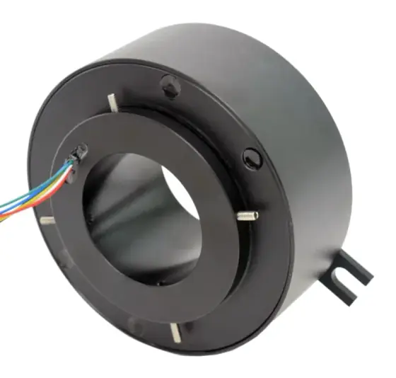
What the slip ring has to handle
- Multi-channel RF rotary joint (waveguide and/or coax) stacked with an electrical slip ring
- RF power handling from hundreds of watts up to megawatt peak in L- and S-band air-traffic radars
- Slip ring ways for antenna electronics, heaters, encoders and data (typically 5 to around 40 ways)
- Optional fibre optic channels for digitised radar data
- Continuous rotation, commonly around 15-60 rpm, with life measured in tens of millions of revolutions
- Wide temperature range and high humidity tolerance for exposed pedestals
- Shock, vibration and EMC qualification for military platforms
Typical figures
| Speed | 60 rpm typical for ATC rotary joints; one 6-channel unit rated 15 rpm; military COTS ring tests at 250 rpm |
|---|---|
| Rf power | ATC rotary joints from 5 W peak to 1.5 MW peak; average up to 11 kW |
| Rf channels | Up to 9 RF channels |
| Slip ring ways | 5 to 38 ways integrated in ATC rotary joints |
| Life | 20-50 million revolutions minimum |
| Temperature | -55 C to +85 C range across ATC models; military COTS rings -40 C to +80 C |
| Ingress protection | IP40 to IP66 (rotating part) |
| Vibration shock | Military COTS test: random vibration 20-2000 Hz at up to 12 g rms; shock 20 g, 11 ms |
Example figures from the published sources listed below. Your requirement may differ; an engineer will confirm against your duty cycle.
Recommended slip ring types
Standards to consider
- MIL-STD-810 - environmental test methods (vibration, shock, temperature) for military radar hardware
- MIL-STD-461 - EMC requirements for military equipment and subsystems
- IEC 60529 - IP code for pedestal enclosures
The complete system
A slip ring rarely works alone. For radar & antenna positioners it is usually specified together with:
- waveguide or coax RF rotary joint
- azimuth drive motor
- servo drive
- absolute encoder
- slewing bearing
- gearbox
- brake
Specifying these together avoids mismatched connectors, cable routes and feedback interfaces, and gives you one point of contact for the whole axis.
Common problems to design out
- VSWR or insertion-loss variation with rotation (wow) on RF channels
- Brush and ring wear after tens of millions of revolutions
- Moisture ingress and corrosion on exposed pedestals
- Crosstalk between RF, data and power paths
Series used in this application
Frequently asked questions
What is the difference between a slip ring and an RF rotary joint?
An RF rotary joint carries microwave signals using waveguide or coax with non-contacting quarter-wave chokes. A slip ring uses sliding contacts for power and lower-frequency signals. Radar pedestals usually stack both in one assembly.
How long do radar rotary joints last?
Air-traffic-control rotary joints are typically specified for 20 to 50 million revolutions minimum at around 60 rpm. Life is driven by total revolutions, environment and sealing.
Can fibre optics pass through a radar rotary joint?
Yes. Rotary joints with singlemode fibre channels at 1310/1550 nm are available, often combined with slip ring ways for power and control.
Sources
- https://en.wikipedia.org/wiki/Waveguide_rotary_joint
- https://militarysystems-tech.com/sites/militarysystems/files/supplier_docs/Air%20Traffic%20Control%20Rotary%20Joints.pdf
- https://www.moog.com/content/dam/moog/literature/MCG/COTSSlipRings.pdf
- https://interferencetechnology.com/introduction-to-mil-std-461g/