
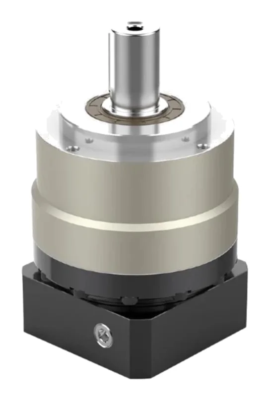
In short:Choose the gearbox type from the geometry and ratio (planetary below about 30:1, strain-wave for compact high ratios, spiral bevel or worm for right angles), set the ratio from motor speed and inertia matching, then size the frame so mean torque, acceleration torque, emergency-stop torque, input speed and output shaft loads all sit inside the catalogue limits with a service factor for shock.
The order to make the decisions in
A servo gearbox multiplies torque, reduces the inertia the motor sees and lets the motor run where it is efficient. Selection goes wrong when a frame is picked on peak torque alone. Work through it in this order:
- Geometry and type: inline or right angle, solid or hollow output, ratio range.
- Ratio: from motor speed and output speed, checked against inertia matching.
- Torque: mean (cube-mean) torque, acceleration torque, emergency-stop torque, with a service or shock factor.
- Precision: backlash class and torsional stiffness against the position tolerance.
- Speed and heat: nominal and maximum input speed, duty and ambient temperature.
- Shaft loads: radial, axial and tilting loads at the real point of application.
- Motor interface: adaptor flange, shaft diameter and length, clamp.
- Environment and life: IP rating, lubricant, washdown, required hours.
Step 1: choose the gearbox type
| Type | Typical ratio per stage | Efficiency (published examples) | Backlash | Where it fits |
|---|---|---|---|---|
| Precision planetary (inline) | about 3:1 to 10:1; two stages to about 100:1 | ≥97% one stage, ≥95% two stage (Wanshsin WSH) | about 1–8 arcmin by class and stages | Most servo axes: gantries, rack and pinion, belts, rotary tables |
| Economy planetary | as above, three stages to 1,000:1 (Apex PG) | lower; check curves | about 8–12 arcmin | Conveyors, general automation where position is not taken through the gear |
| Spiral bevel right-angle planetary | 3:1 to 200:1 | ≥95% one stage, ≥92% two stage (Wanshsin WSHR) | about 4–9 arcmin | Where the motor must fold back alongside the machine |
| Strain-wave (harmonic) | about 30:1 to 160:1 in one stage | speed, load and temperature dependent; lower than planetary | zero by design | Compact high-ratio joints, hollow-shaft axes |
| Worm | commonly about 5:1 to 60:1 in one stage (12:1 to 60:1 for our worm wheel range) | falls steeply as ratio rises (see below) | moderate, grows with wear | Low-cost right-angle drives, slow duty, small DC gearmotors |
For the detailed trade-off between strain-wave, planetary and cycloidal reducers, including stiffness and life calculations, see our strain-wave vs planetary vs cycloidal comparison.
Worm gearboxes need a special word. Boston Gear gives worm efficiency as E = tan γ (1 − f tan γ) / (f + tan γ), where γ is the lead angle and f the friction coefficient, suggesting about 0.03 to 0.05 for a hardened steel worm on bronze (Boston Gear). With f = 0.05, a 20° lead angle gives about 86%, but a 5° lead angle (typical of high ratios) gives only about 63%. The lost power becomes heat, so worm boxes suit intermittent duty where efficiency is not critical.
Step 2: set the ratio from speed and inertia
Start with speed:
i = n_motor / n_output
where n_motor is the speed you want the motor to run at the top of the move. Leave headroom below the motor’s maximum speed for the drive’s voltage limit and for tuning overshoot.
Then check inertia. Reflected load inertia falls with the square of the ratio:
J_reflected = J_load / i²
Most servo sizing guidance targets a load-to-motor inertia ratio of 10:1 or less, and lower for very dynamic, high-precision axes (Motion Control Tips; Stöber via CDA). Rearranged, the ratio that hits a target inertia ratio is:
i = √( J_load / (J_ratio × J_motor) )
If speed and inertia disagree, use a faster motor (allowing a higher ratio), a motor with more rotor inertia, or accept a higher inertia ratio with a stiffer drive train. Compliance in belts and couplings, more than the drive, usually sets the limit.
Step 3: size for torque, with the right factors
Build the output torque cycle (acceleration, constant speed, deceleration, dwell, each with duration and speed), then calculate:
- Peak acceleration torque T_acc = J_load × α + friction + gravity (at the gearbox output).
- Cube-mean torque, speed-weighted: T_m = ( Σ nᵢ tᵢ |Tᵢ|³ / Σ nᵢ tᵢ )^(1/3). Bearing and gear life follow a cube law, so the mean is a cube root, not an RMS (Machine Design).
- Emergency-stop or crash torque: the worst event the gearbox must survive, usually set by the motor’s peak torque × ratio × efficiency, or by a mechanical jam.
Then compare with the catalogue:
| Calculated value | Must be within | Notes |
|---|---|---|
| Cube-mean torque | T2N (nominal output torque) | Sets life |
| Peak cyclic torque × shock/operating factor | T2B (max acceleration torque) | Apex lists T2B as 60% of T2NOT |
| Crash / E-stop torque | T2NOT (emergency-stop torque) | WITTENSTEIN: no more than 1,000 times in the life; Apex: 3 × T2N |
Sources: Apex Dynamics; WITTENSTEIN alpha.
Service and shock factors. For industrial gear units on electric motors, an AGMA-style table sets the factor by load character and running hours. AutomationDirect’s IronHorse manual, for example, uses 1.00 for uniform loads up to 10 hours a day, 1.25 for moderate shock beyond 10 hours, and up to 2.00 for extreme shock over 10 hours (AutomationDirect). Stöber’s guidance is that 1.4 is adequate for most industrial applications, and that cyclic and reversing duty need more (CDA). Servo planetary makers apply their own factors based on cycles per hour; use the method of the gearbox you are buying.
Limit the motor. Servo peak torque × ratio can exceed T2NOT. Set the drive torque limit so motor peak × ratio × efficiency stays under it.
Step 4: choose the backlash class
Convert the load tolerance into an angle at the gearbox output. For a pinion or pulley of radius r:
linear error = angle (rad) × r, and 1 arcmin = 2.909 × 10⁻⁴ rad.
At r = 30 mm, 1 arcmin is about 9 µm. A 3 arcmin gearbox can therefore move a rack-driven carriage by around ±25 µm on torque reversal before any rack backlash, belt stretch or wind-up is counted.
Precision planetaries are sold in classes. Wanshsin’s WSH, for example, lists P0 ≤1.5, P1 ≤3 and P2 ≤5 arcmin for one stage, rising to 3, 5 and 8 arcmin for two stages. Right-angle versions start higher because the bevel stage adds its own lash. If the axis never reverses torque near its stopping point (a vertical axis holding against gravity, say), stiffness matters more than backlash.
Step 5: input speed, duty and heat
Every gearbox has a nominal input speed for continuous running and a higher maximum input speed for short cyclic moves. WITTENSTEIN alpha states that the nominal input speed must not be exceeded in continuous operation, is limited by a 90 °C housing temperature, and is quoted at 20 °C ambient; higher ambients need a lower speed (WITTENSTEIN alpha).
Check the mean input speed over the cycle against the nominal value, and the peak against the maximum. Axes that run continuously at speed (conveyors, winders, spindles) are often limited by heat before torque.
Step 6: radial, axial and tilting loads
A pulley, pinion or crank on the output shaft loads the output bearings. Catalogue radial ratings normally apply at a defined point, often the shaft midpoint; Apex quotes its rating with the force at the centre of the output shaft and gives a correction factor for other positions (Apex Dynamics). Move the load further out and the allowable force falls.
Include the forces that are easy to forget:
- Belt pretension, which is often larger than the working belt pull.
- Gear separating force on a pinion: for a 20° pressure angle, the radial component is about 0.36 × the tangential tooth force.
- Drive element factors: for industrial gear units, AutomationDirect divides the overhung load rating by 1.00 for chain and sprocket, 1.25 for gears, 1.50 for V-belts and 2.50 for flat belts (AutomationDirect).
If loads exceed the output bearing, carry them on a separate bearing and couple the gearbox through a flexible element.
Step 7: the motor adaptor
Servo planetaries come with an adaptor flange and input clamp for a named motor; Apex, for example, takes the motor designation in the order code and clamps with a split collet (Apex Dynamics). Send the motor model, or its flange pilot, bolt circle, shaft diameter, length and key. Motor shaft engagement is one of the checks Stöber lists for servo applications (CDA): a shaft too short for the clamp slips and frets.
Worked example: rack-and-pinion gantry axis
Requirement: Horizontal gantry axis. Moving mass 400 kg. Pinion pitch radius 31.83 mm (200 mm per revolution). Top speed 2 m/s, acceleration 5 m/s². Friction and drag about 200 N. Cycle: accelerate, run, decelerate, dwell, 2.0 s total. Position tolerance at the carriage ±0.05 mm. Servo motor rated to about 4,500 rpm, with an assumed rotor inertia of 10 kg·cm² for this example (use your motor’s datasheet value).
Output speed: 2 / 0.2 = 10 rev/s = 600 rpm.
Ratio from speed: running the motor at about 4,200 rpm gives i = 4,200 / 600 = 7:1.
Inertia: load inertia at the pinion J = m r² = 400 × 0.03183² = 0.405 kg·m². Reflected: 0.405 / 7² = 0.0083 kg·m² = 83 kg·cm², an inertia ratio of about 8:1 against a 10 kg·cm² rotor. Inside the 10:1 target. A 5:1 ratio would give 16:1, which is why the higher-speed motor was chosen.
Torque cycle at the gearbox output:
- Acceleration (0.4 s, mean 300 rpm): F = 400 × 5 + 200 = 2,200 N, so T = 2,200 × 0.03183 = 70 Nm
- Constant speed (0.6 s, 600 rpm): 200 N, so 6.4 Nm
- Deceleration (0.4 s, mean 300 rpm): 2,000 − 200 = 1,800 N, so 57 Nm (reversed)
- Dwell (0.6 s): 0 Nm
Cube-mean torque: Σ n t T³ = 300×0.4×70³ + 600×0.6×6.4³ + 300×0.4×57.3³ ≈ 63.8 × 10⁶; Σ n t = 600. T_m = (106,400)^(1/3) ≈ 47 Nm.
Mean input speed: the pinion turns 0.4 × 5 + 0.6 × 10 + 0.4 × 5 = 10 revolutions in the 2 s cycle, an average of 300 rpm. The input averages 300 × 7 = 2,100 rpm, to be checked against the nominal input speed for the frame.
Crash torque: if the motor can deliver 20 Nm peak, 20 × 7 × 0.97 ≈ 136 Nm could reach the output in a jam. Either size T2NOT above that or set the drive torque limit lower.
Radial load on the output: tangential tooth force 2,200 N plus separating force 2,200 × tan 20° ≈ 800 N, a resultant of about 2,340 N at the pinion’s position on the shaft. Check against the radial rating corrected for that position.
Backlash budget: ±0.05 mm at 31.83 mm radius is ±1.57 × 10⁻³ rad, about ±5.4 arcmin in total. The rack and pinion mesh, wind-up and gearbox all share it. A one-stage P1 class (≤3 arcmin) leaves margin; a P2 (≤5 arcmin) would use almost the whole budget.
Selection: a one-stage inline precision planetary at 7:1, P1 class, in the smallest frame with T2N above 47 Nm, T2B above 70 Nm after the shock factor, T2NOT covering the crash case and a radial rating above 2.3 kN at the pinion position. A range built for radial load, such as the Wanshsin WTH, is a natural first look.
Products in our range to consider
- Wanshsin WSH: high-rigidity inline planetary, three backlash classes down to ≤1.5 arcmin one stage, up to 2,400 Nm rated.
- Wanshsin WTH: inline planetary designed for high radial loads, up to 2,050 Nm rated, ≥97% efficiency one stage.
- Wanshsin WSHR: right-angle WSH with a spiral bevel stage, ratios 3:1 to 200:1.
- Apex AD / ADR / ADS: high-precision short planetary with accuracy quoted at under 1 arcmin.
- Apex AE / AER / AES / AESR: helical planetary inline and right angle, with all-stainless AES/AESR versions for washdown.
- Apex P-II / P-IIR: economy planetary family, ratios 3:1 to 1,000:1, rated to 459 Nm.
- Apex GL / GLS: AGV planetary with a rotating housing for direct wheel mounting, radial load to 7,200 N.
- Wanshsin WTN: hollow-shaft rotary platform reducer with crossed roller bearing, backlash ≤0.5 arcmin.
- Leaderdrive LHS / LHSG: hollow-shaft strain-wave gear units, ratios 30:1 to 500:1.
- Worm wheel gearbox for ZYT DC motors: compact worm gearboxes in die-cast aluminium or composite housings, ratios 12:1 to 60:1, brake option.
What else the build needs
- Motor: servo or stepper, chosen together with the ratio. See servo and stepper motors and servo vs stepper.
- Drive: with a torque limit set to protect the gearbox. See servo drives.
- Feedback: a motor encoder for commutation, and an output-side or linear encoder if backlash and wind-up must be removed from the position loop. See encoders and absolute vs incremental encoders.
- Brake: on vertical or back-drivable axes, ideally on the motor side where torque is lowest.
- Couplings, pinions and pulleys rated for the output torque.
- Controller for multi-axis coordination: see motion controllers.
- For linear motion, compare a gearbox and rack against a complete actuator in our linear actuator sizing guide.
Things that catch engineers out
- Sizing on peak torque alone. The cube-mean sets life, and the crash case sets survival. Check all three limits.
- Not limiting motor torque. A big servo on a high ratio can break the gearbox it was meant to protect.
- Running a short-cycle gearbox continuously. The maximum input speed is not a continuous rating; heat is.
- Radial load at the wrong point. A pinion mounted at the end of a long shaft sees a much lower allowable load than the catalogue headline.
- Forgetting belt pretension. It often exceeds the working load.
- Relying on a worm to hold a load. Vibration can let it back-drive. Fit a brake.
- Stacking backlash. Gearbox, rack, coupling and wind-up all add. Budget the whole chain.
- Mounting orientation. State it when ordering; vertical shafts can need a different lubricant fill.
Checklist
Send these to our engineers, or enter them in the spec builder:
- Inline or right-angle, solid or hollow output, any envelope limits
- Motor make and model (or flange, shaft size and length)
- Required output speed and the motor speed you want to run at
- Load inertia at the gearbox output and the inertia ratio you are aiming for
- Torque cycle: values, speeds and durations for each segment
- Peak and crash or emergency-stop torque, and the drive’s torque limit
- Cycles per hour, hours per day and the type of shock (reversing, jams, impacts)
- Backlash class or position tolerance at the load, and the radius it applies at
- Radial and axial loads, with their distance from the output flange
- Ambient temperature, IP rating, washdown or food-grade lubricant needs
- Mounting orientation
- Required life in hours
For the wider family, see our gearboxes overview.
Frequently asked questions
What gear ratio do I need for a servo motor?
Start with ratio = motor speed at your chosen operating point ÷ required output speed. Then check reflected inertia: load inertia divided by the ratio squared, compared with the motor rotor inertia. Most servo sizing guidance aims for a load-to-motor inertia ratio of 10:1 or less, lower for very dynamic axes. If speed and inertia point to different ratios, change the motor or accept a compromise and tune for it.
What is the difference between T2N, T2B and T2NOT?
T2N is the nominal output torque the gearbox can carry continuously for its rated life. T2B is the maximum acceleration torque allowed during normal cyclic operation. T2NOT is the emergency-stop torque: an occasional overload, not part of the cycle. WITTENSTEIN alpha, for example, states that T2NOT must not be reached more than 1,000 times during the life of the gearhead and must never be exceeded.
What service factor should I use for a gearbox?
It depends on shock and daily running hours. A typical AGMA-style table, such as the one in AutomationDirect's IronHorse manual, runs from 1.00 for uniform loads up to 2.00 for extreme shock over 10 hours a day. Servo planetary makers use their own operating or shock factors tied to cycles per hour. Always use the factor method from the catalogue of the gearbox you are buying.
Is a worm gearbox self-locking?
Sometimes, statically, but never rely on it. Boston Gear says a lead angle below 5° gives a reasonable expectation of self-locking but no guarantee, and that back-driving may be expected above 11°. Vibration and shock can lower mesh friction enough for a load to run back. If a load must be held, fit a brake.
How much backlash is acceptable?
Convert the position tolerance at the load into an angle at the gearbox output. At a 30 mm pinion radius, 1 arcmin is about 9 µm of linear movement. If the axis reverses torque near its stopping point, backlash and wind-up both land inside the tolerance, so allow for both. Precision planetaries are offered in classes, typically from about 1 to 8 arcmin depending on stages and grade.
Why does a gearbox have a nominal input speed?
Churning losses and seal friction heat the gearbox as input speed rises. WITTENSTEIN alpha states that the nominal input speed must not be exceeded in continuous operation and is limited by a 90 °C housing temperature, with the catalogue value valid at 20 °C ambient. Short cyclic moves can use the higher maximum input speed; long runs at speed cannot.
Sources
- Motion Control Tips (Danielle Collins): How do I determine what gear ratio I need for my servo system?
- WITTENSTEIN alpha: alpha Value Line NP catalogue (US), glossary and sizing
- AutomationDirect: IronHorse helical bevel gearbox user manual, chapter 2 (service and overhung load factors)
- Controls Drives Automation: Stöber gearbox sizing to the load
- Machine Design: The essentials of sizing and applying planetary servo gears
- Apex Dynamics: AE/AER series catalogue (ManualMachine copy)
- Boston Gear: Engineering information, worms and worm gears
- Machine Design (A. V. Karvelis): Self-locking worm gears, fact or fiction?
Figures are summarised from the sources above and from manufacturers' published data on the date shown. Always confirm against the current datasheet for your exact part.