
In short:Pick open or closed loop first, then match the drive's phase current to the motor and choose the highest supply voltage the motor and drive allow, because voltage, set against winding inductance, is what holds torque at speed. Choose microstepping for smoothness rather than accuracy, check that the controller's pulse rate or fieldbus can command the speed you need, and only then pick the form factor.
A stepper drive does three jobs: it regulates current in each motor phase, sequences that current to move the rotor, and takes commands from your controller. The motor and drive work as a pair, so a stepper’s torque at speed depends as much on the drive’s voltage and current control as on the motor itself. If you have not yet settled on steppers rather than servos, start with servo vs stepper.
Step 1: Open loop or closed loop
Decide this first, because it narrows both the motor and the drive range.
- Open loop. The drive assumes the rotor follows. Lowest cost, simplest set-up. If the load exceeds available torque the motor loses steps and nothing tells the controller. Kollmorgen’s guidance is to size open-loop steppers at about twice the continuous torque requirement for this reason (Kollmorgen).
- Closed loop. An encoder on the motor lets the drive detect and correct position error, alarm on a stall, and in many designs reduce current when the load is light, so the motor runs cooler and quieter. It cannot create torque the motor does not have at that speed.
Rule of thumb: if a lost step would scrap product, crash tooling or go unnoticed until the end of a batch, specify closed loop. If the axis is a lightly loaded adjustment or set-up axis, open loop is usually fine.
Step 2: Match phase current to the motor
Set the drive’s output current to the motor’s rated phase current, and choose a drive whose range brackets it with some room to spare.
- Check rms or peak. Some drives set current as peak, some as rms; motor datasheets may use either. Getting this wrong runs the motor at 70% or 141% of rating.
- Eight-lead motors can be wired series or parallel. Series wiring uses lower current but quadruples inductance compared with parallel, so it gives more low-speed torque per amp and much less torque at speed. Parallel wiring needs more drive current but holds torque to higher speed.
- Idle current reduction lowers heat at standstill but also lowers holding torque. Make sure the reduced current still holds the load, particularly on vertical axes.
- Phase count: two-phase drives for standard 1.8° and 0.9° motors; three-phase and five-phase (0.72°) motors need matching drives.
Step 3: Choose supply voltage against inductance
This is the step most often got wrong. A stepper’s torque falls with speed because winding inductance limits how fast current can build in each step. The electrical time constant is τ = L ÷ R. Raising the supply voltage drives current in faster and holds torque to higher speed, which is why pull-out curves are always quoted at a specific voltage.
- A widely quoted rule of thumb sets the maximum supply at V_max ≈ 32 × √L, with L in mH. A 4 mH motor gives about 64 V DC (LinuxCNC). Above this, iron losses and heating rise. Treat it as a starting point and check motor temperature in testing.
- Stay below the drive’s maximum input, with headroom for supply tolerance and for energy returned when the motor decelerates a load. A nominal 48 V supply on a 50 V maximum drive leaves almost no margin.
- Supply current is usually less than you expect. Applied Motion puts the upper bound at twice the motor phase current per axis, and notes that a 48 V supply draws roughly half the current of a 24 V supply for the same motor (Applied Motion).
- For large NEMA 34 and 42 motors, consider an AC-input or high-voltage drive (80–110 V DC or rectified mains) to get torque at speed.
Step 4: Microstepping, smoothing and resonance
Microstepping divides each 1.8° step by shaping phase currents into approximate sine waves. It gives smoother motion, less noise and less excitation of resonance. It does not give proportional accuracy.
The torque available to move one microstep is T_inc = T_hold × sin(90° ÷ microsteps per full step). At 1/16 step that is about 9.8% of holding torque, and at 1/256 about 0.6% (Machine Design). Detent torque, typically 5 to 20% of holding torque, also distorts position between full steps. Monolithic Power’s tests at 1/32 step found some microsteps produced no motion until several had accumulated under load (MPS).
Practical rules:
- Choose microstepping for smoothness, typically 1/8 to 1/32. Do not rely on it for positions finer than a few microsteps.
- Use command smoothing or microstep interpolation in the drive if your controller can only output coarse pulses.
- Mid-range resonance, typically around 6 to 15 rev/s on a 200-step motor, can stall an open-loop motor within a second (Dover Motion). If the axis cruises in that band, specify a drive with anti-resonance control or go closed loop.
Step 5: Check pulse rate or fieldbus
Pulse and direction is still the most common interface. The step frequency you need is:
f = (rpm ÷ 60) × full steps per rev × microsteps per full step
A 1.8° motor at 1,500 rpm on 1/16 needs 80 kHz; on 1/128 it needs 640 kHz. Many drives accept around 200 kHz, and compact PLC pulse outputs can be lower still, so check both ends. Use differential (line-driver) signals over long cables.
Networked drives remove the pulse-rate limit and add diagnostics:
| Interface | Good for |
|---|---|
| Modbus RTU (RS485) with position table | Simple indexing axes triggered by I/O or a small PLC |
| CANopen (CiA 402) | Low-voltage machines, lab automation, AGVs |
| EtherCAT (CiA 402) | Multi-axis machines mixing steppers and servos on one network |
| EtherNet/IP, PROFINET | Plants standardised on Rockwell or Siemens controllers |
Multi-axis drives (two or four axes per unit) cut wiring and cost on gantries and multi-station machines. If the axis must run on its own with no PLC, look for a drive with an integrated controller that stores programs or position tables.
Step 6: Form factor and environment
- DIN-rail or panel drives: the standard choice for cabinets.
- Integrated steppers: motor, drive and often encoder and controller in one unit. They save cabinet space and cable runs on distributed machines, but put the drive’s heat at the motor and make the motor the replaceable unit.
- Miniature, flange-mounted drives bolt to the back of the motor, a middle route between panel and integrated.
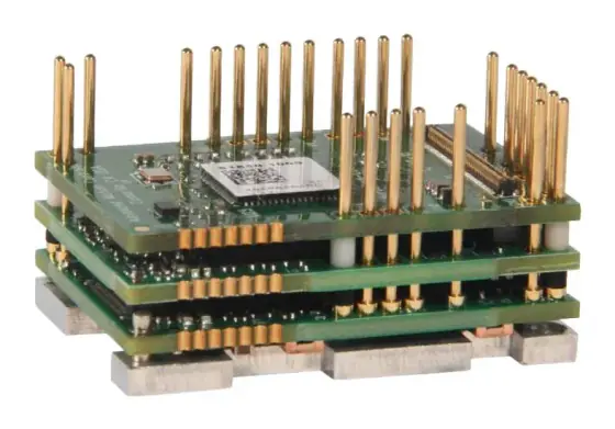
- PCB-mount drives and modules: solder or plug onto your own board for instruments, medical devices and high-volume OEM products. You design the thermal path, connectors and EMC.
- Environment: ambient temperature and derating, IP rating, conformal coating, and whether the motor connector suits wash-down.
Worked example: a NEMA 23 conveyor index axis
Axis: NEMA 23 two-phase hybrid stepper, parallel-wired, 3.0 A per phase, phase inductance 2.5 mH, resistance 0.8 Ω (take the real figures from your motor datasheet). It indexes a light conveyor at up to 750 rpm. Three identical axes share a supply. The controller is a small PLC with pulse outputs limited to 100 kHz.
Voltage:
- Rule-of-thumb maximum: 32 × √2.5 ≈ 51 V
- Time constant τ = 2.5 mH ÷ 0.8 Ω ≈ 3.1 ms
- A 48 V supply suits the motor, but on a drive with a 50 V maximum it leaves no margin for tolerance or regenerated energy. Choose a drive rated to 80 V DC and run it at 48 V, or run a 50 V drive at 36 V and accept less torque at speed. Check the pull-out curve at whichever voltage you choose.
Pulse rate:
- 750 rpm = 12.5 rev/s
- At 1/16 microstepping: 12.5 × 200 × 16 = 40 kHz. Fine for the PLC.
- At 1/64: 160 kHz. Beyond the PLC’s 100 kHz output. Either stay at 1/16 and use the drive’s smoothing, or move to a networked drive.
Resonance: 12.5 rev/s sits inside the typical 6–15 rev/s mid-range band. Specify a drive with anti-resonance control and test with the real conveyor load, or use closed loop.
Supply: upper bound 2 × 3.0 A × 3 axes = 18 A at 48 V. Real draw will be well below this. Measure it on the prototype across the duty cycle and size the production supply from the measurement, keeping the 18 A figure as the worst case.
Choice: a Leadshine EM-S 80 V model at 48 V, 1/16 microstepping, anti-resonance on. If a stalled conveyor must be detected, step up to the CS-D closed-loop drive with a CS-M motor, or put all three axes on EtherCAT with CS3E drives and drop the pulse-rate limit entirely.
Products in our range to consider
- Leadshine EM-S series: open-loop pulse/direction drives from 1.5 to 8.2 A, 200 kHz input, anti-resonance and up to 25,600 steps/rev by DIP switch.
- Leadshine CS-D series: closed-loop pulse/direction drives for CS-M encoder motors, up to 8 A and 110 V DC.
- Leadshine CS3E series: single-axis closed-loop EtherCAT (CiA 402) stepper drive, up to 8 A, with CSP, PP, PV and homing modes.
- Leadshine EM2RS series: open-loop Modbus RTU drive with a 16-segment position table, up to 31 drives per RS485 network.
- Leadshine 4EM3E series: four-axis open-loop EtherCAT stepper drive, up to 8.2 A per axis.
- Leadshine iCS integrated closed-loop steppers: motor, 14-bit encoder and drive in one unit, NEMA 17 to 24, up to 3.5 Nm.
- Novanta Liberty MDrive: integrated stepper in NEMA 17, 23 and 34 with pulse, RS-422/485, CANopen, EtherNet/IP, PROFINET or Modbus TCP versions and IP65 options.
- Novanta MForce: compact 12–48 V or 12–75 V drives at 3 or 5 A rms, in step/direction, programmable or CANopen versions.
- Novanta IM483H / IM805H: PCB-solder microstepping drivers at 48 V/3 A rms and 75 V/5 A rms, up to 51,200 steps/rev.
- UI Robot UIM242: miniature motor-mounted CAN 2.0B controller/drive up to 8 A, with an onboard pulse generator and encoder closed loop.
What else the build needs
- Motor: a hybrid stepper with the right frame, winding and encoder option. See servo and stepper motors.
- Power supply: sized for voltage headroom and peak current, with a regen clamp if large inertias decelerate quickly.
- Encoder: built into closed-loop motors, or a separate load-side encoder. See encoders.
- Gearing or screw: a planetary gearbox to reduce reflected inertia, or a lead or ball screw. See gearboxes and ball screw vs roller screw.
- Brake: for vertical axes, as idle current reduction or power loss will drop the load.
- Cabling: shielded motor cable, kept away from the pulse and encoder lines.
- Controller: a PLC with fast pulse outputs or a fieldbus master. See motion controllers and how to select a motion controller or PLC.
Things that catch engineers out
- Sizing from holding torque instead of the pull-out curve at your speed and voltage.
- Running at a lower voltage than the torque curve was measured at.
- A 48 V supply on a 50 V drive, which trips or fails when the supply runs high or the motor regenerates.
- Setting peak current on a drive that expects rms, or the reverse.
- High microstep settings that exceed the PLC’s pulse output at top speed, so the axis never reaches it.
- Cruising in the mid-range resonance band without anti-resonance or closed loop.
- Idle current reduction on a vertical axis that lets it creep or drop.
- Long, unshielded pulse cables that pick up noise and add phantom steps.
Checklist
Send these to our engineers, or enter them in the spec builder:
- Motor frame, phase current, inductance and wiring (or the torque and speed you need)
- Open loop or closed loop, and what should happen on a stall
- Supply available, and any limit on voltage
- Top speed and the speed the axis spends most time at
- Resolution and accuracy actually required at the load
- Controller and interface: pulse rate available, Modbus, CANopen, EtherCAT, EtherNet/IP, PROFINET
- Number of axes and whether multi-axis drives would help
- Form factor: DIN-rail, integrated, motor-mounted or PCB
- Holding requirement, brake, vertical loads
- Environment, IP rating, volume and cost target
Frequently asked questions
What supply voltage should I use for a stepper motor?
Use the highest voltage that both the drive and the motor's insulation allow, because higher voltage pushes current into the winding faster and holds torque to higher speed. A widely quoted rule of thumb sets the maximum at 32 times the square root of the winding inductance in mH, so a 4 mH motor tops out around 64 V DC. Always leave headroom below the drive's maximum input.
Does microstepping make a stepper more accurate?
Not by much. It increases resolution and smoothness, but the torque available for each microstep falls quickly: at 1/16 step each microstep produces only about 10% of holding torque, so friction or load can stop small steps from happening. Detent torque and imperfect current waveforms also add error. Use microstepping to reduce noise and resonance, not as a route to accuracy.
Should I choose an open-loop or closed-loop stepper drive?
Choose closed loop when a lost step would scrap product, crash tooling or go unnoticed, or when you want the motor to run cooler by scaling current to load. Choose open loop for simple, lightly loaded axes where cost and simplicity matter most and the move is well inside the motor's pull-out curve. Size open-loop systems with about twice the torque you need.
How much current does a stepper drive power supply need?
Less than the phase current suggests, because the drive is a switching amplifier. Applied Motion puts the upper bound at twice the motor's phase current per axis and notes that real draw is usually much lower, depending on voltage, speed and load. A higher supply voltage reduces supply current for the same motor power. For production machines, measure actual draw before choosing a smaller supply.
What pulse frequency does a stepper drive need?
Multiply revolutions per second by full steps per revolution and by the microstep setting. A 1.8° motor at 1,500 rpm on 1/16 microstepping needs 25 × 200 × 16 = 80 kHz. At 1/128 it needs 640 kHz, beyond many drives' 200 kHz input and many PLC pulse outputs. Check both the drive input limit and the controller's output limit.
When should I use an integrated stepper motor?
When cabinet space, wiring cost or cable length is the problem. An integrated stepper puts the drive, and often a controller and encoder, on the motor, so you run only power and a network or I/O cable. They suit distributed axes on packaging, lab and conveyor equipment. Check heat at the motor, IP rating, and service: a drive fault means replacing the whole unit.
Sources
- Machine Design: Microstepping myths
- Monolithic Power Systems: Why microstepping isn't as good as you think
- LinuxCNC documentation: Stepper motor operation
- Applied Motion Products: STR4 user manual, choosing a power supply
- Kollmorgen: Servo or stepper? Selection guide (WP-000286)
- Dover Motion: Midrange resonance
Figures are summarised from the sources above and from manufacturers' published data on the date shown. Always confirm against the current datasheet for your exact part.